Waste Oil Electrical Generation Systems

a technology of electrical generation system and waste oil, which is applied in the direction of machines/engines, combustion types, lighting and heating apparatuses, etc., can solve the problems of waste oil dumping becoming a major worldwide environmental issue, waste oil can contaminate up to one million gallons of water, and the efficient burning of waste oil is a relatively complex problem

Inactive Publication Date: 2011-01-06
BASSETT TERRY EDGAR
View PDF34 Cites 23 Cited by
  • Summary
  • Abstract
  • Description
  • Claims
  • Application Information

AI Technical Summary

Problems solved by technology

Waste oil dumping has increasingly become a major worldwide environmental issue.
It has been shown that one gallon of waste oil can contaminate up to one million gallons of water.
Efficient burning of waste oil is a relatively complex problem.
Despite the high level of efficiency of current waste oil burners, as much as seventy percent of the combustion heat produced by a unit is lost as exhaust.

Method used


Image

  • Waste Oil Electrical Generation Systems
  • Waste Oil Electrical Generation Systems
  • Waste Oil Electrical Generation Systems

Examples


Embodiment Construction

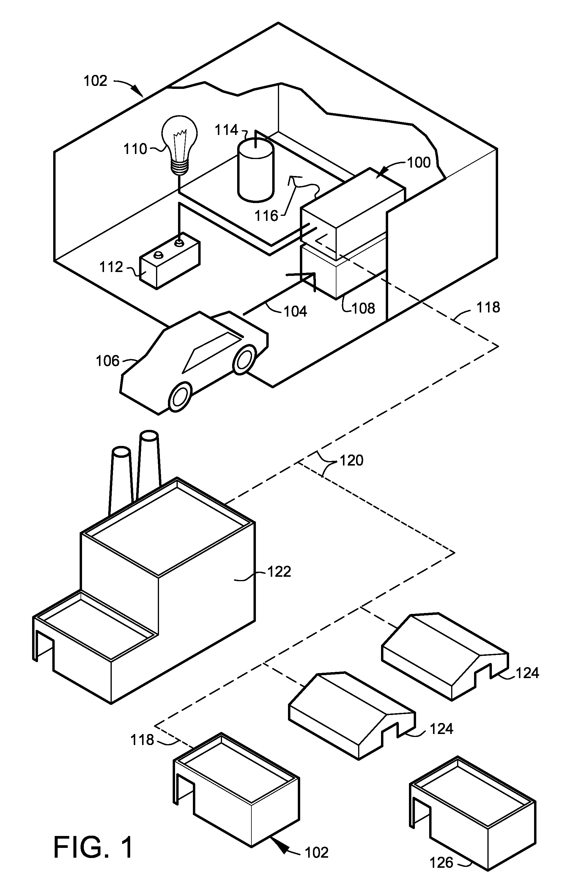
[0044]FIG. 1 is a diagrammatic perspective view, illustrating in general, a typical organization of distributed cogeneration site(s) 102 linked to a larger electrical power grid 120, as well as remote waste oil electrical cogeneration site(s) 126, independent from a larger power distribution system, according to a preferred embodiment of the present invention.

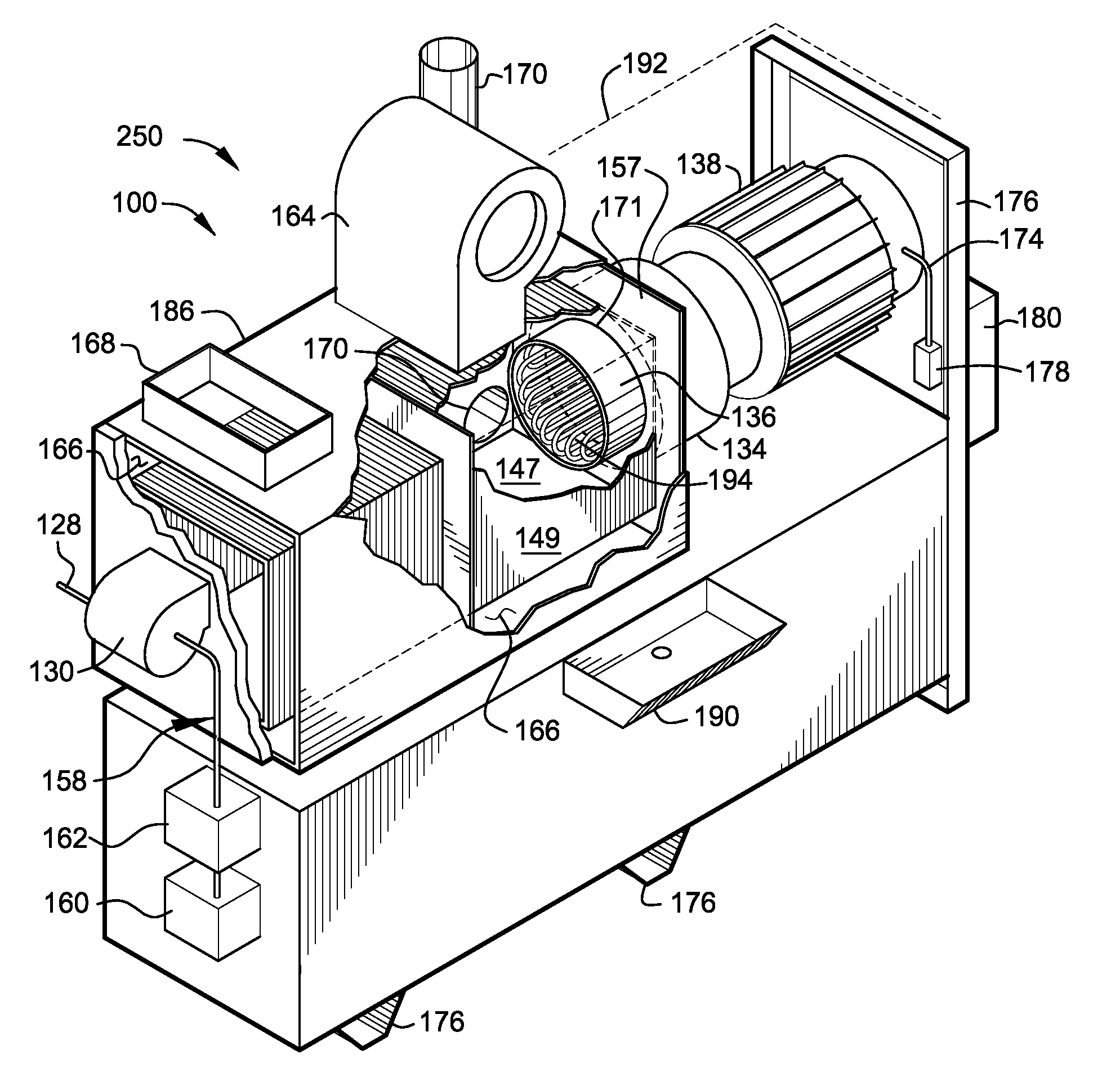
[0045]The enlarged cut-away view of distributed cogeneration site 102 (in the upper portion of FIG. 1) illustrates, in general, the preferred operational and mechanical arrangements that make up a distributed cogeneration site utilizing waste oil generated on-site as a source of useable energy. In the present disclosure the term “on-site” shall include in the definition the taking place or located at a site comprising waste oil cogeneration system 100.

[0046]Preferably, a significant portion of the on-site electrical power 110 used within the local electrical network of distributed cogeneration site 102 (at least embodying herei...


PUM


Abstract

An on-site electrical power generation system utilizing environmentally hazardous waste oils as a combustible fuel. The disclosed invention utilizes the combustion of environmentally hazardous waste oils to drive a heat engine and electrical generator. In addition, the system is adapted to provide local space heating and hot water as a byproduct of the combustion process.

Description

CROSS-REFERENCE TO RELATED APPLICATION[0001]The present application is related to and claims priority from prior provisional application Ser. No. 61 / 222,211, filed Jul. 1, 2009, entitled “WASTE OIL ELECTRICAL GENERATION SYSTEMS”; and, this application is related to and claims priority from prior provisional application Ser. No. 61 / 292,480, filed Jan. 5, 2010, entitled “WASTE OIL ELECTRICAL GENERATION SYSTEMS”, the contents of all of which are incorporated herein by this reference and are not admitted to be prior art with respect to the present invention by the mention in this cross-reference section.BACKGROUND[0002]This invention relates to providing an improved electrical generation system utilizing waste oil as a combustible fuel. More particularly, this invention relates to the co-generation of electrical power using a generator powered by the heat energy produced by a waste-oil-fired furnace.[0003]Well over a billion gallons of used oil are generated in the United States each ye...

Claims


Application Information

Patent Timeline
Patent Type & Authority Applications(United States)
IPC IPC(8): F23G7/05F01K27/00
CPCF01K7/36Y02T10/166F01K25/10F23D11/106F23D11/24F23G7/05F23G2206/202F23G2206/203F23K5/08F23K2301/204F23K2301/206F23K2900/05001Y02E20/12Y02T10/16F01K7/38F23K2300/204F23K2300/206Y02T10/12
Inventor BASSETT, TERRY EDGAR
Owner BASSETT TERRY EDGAR
Why Eureka
Try Eureka