
Pop-up lift pedestal for a television

a technology for a television and a pedestal is applied in the field of pop-up lift pedestals for tvs, which can solve the problems of complicated and expensive electro-mechanical devices designed for custom home theater applications, and achieve the effects of smooth stable transportation of the tv, reliable and cost-effective, and increased effective travel of the gas prop piston

Inactive Publication Date: 2011-01-06
GARDNER STEWART E
View PDF13 Cites 17 Cited by
  • Summary
  • Abstract
  • Description
  • Claims
  • Application Information

AI Technical Summary

Benefits of technology

[0004]The present invention provides a reliable and cost effective lift pedestal for raising and lowering a television or video monitor between a retracted storage position and an extended viewing position. The lift pedestal is ideal for mobile home applications and home theater applications where cost and space restrictions are a principle concern. The lift pedestal can be incorporated into any suitable piece of furniture or cabinetry. In addition the lift pedestal can be mounted directly to any wall or vertical support structure. The lift pedestal can also be used as a stand alone support device or incorporated into cabinetry or a furniture enclosure.
[0005]One embodiment of the lift pedestal of this invention includes a stationary back plate and an extensible support plate to which the television or video monitor is mounted. A pair of cabinetry drawer slides allow vertical translational movement of the support plate relative to the back plate between the retracted storage position and the extended viewing position. The drawer slides are mounted between angled sides of the back plate and support plate. The lif...

Problems solved by technology

A variety of complicated lift devices have been developed to raise and lower televisions and video monitors from cabinetry and other furniture pieces, but these devices have been complicated and expensive electro-mechanical devices designed for custom home theater applications.

Method used


Image

  • Pop-up lift pedestal for a television
  • Pop-up lift pedestal for a television
  • Pop-up lift pedestal for a television

Examples


Embodiment Construction

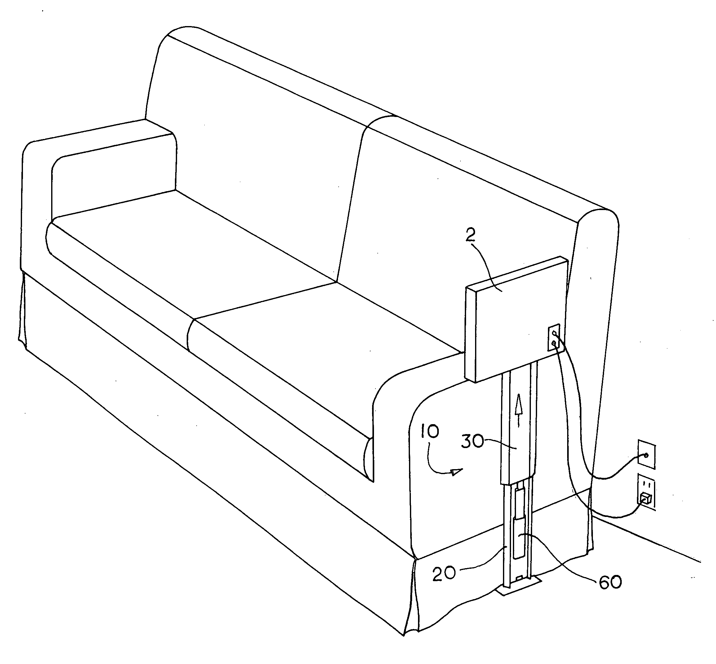
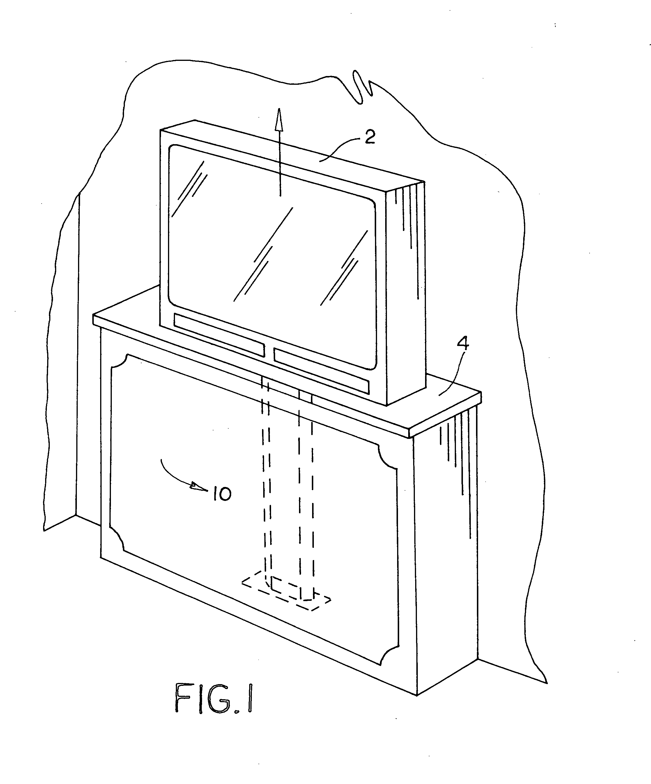
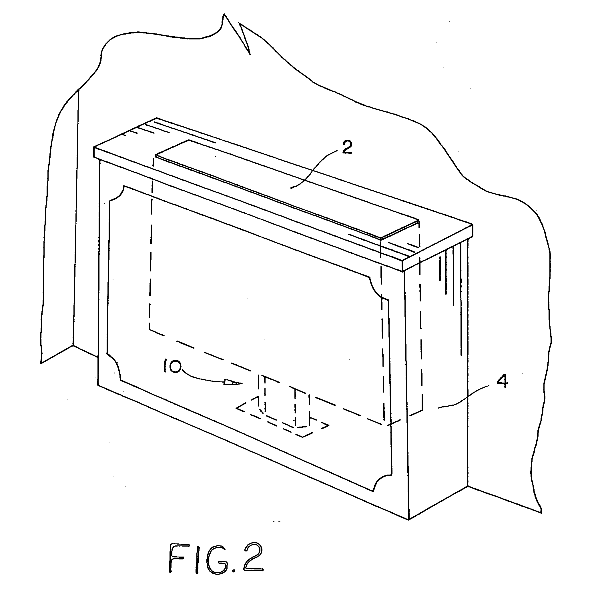
[0027]Referring now to the drawings, reference numeral 10 in FIGS. 1-11 generally designates an embodiment of the lift pedestal of this invention. Lift pedestal 10 is used to raise and lower a television, video monitor or other device between an extended or raised position and a retracted or lowered position. Lift pedestal 10 is designed to be incorporated into cabinetry or a furniture enclosure (FIGS. 1 and 2) or used as a stand alone support device (FIGS. 3 and 4). Typically, lift pedestal 10 elevates the television or monitor from the furniture enclosure into the extended position for viewing and lowers the television or monitor into the furniture enclosure into the retracted position for storage.

[0028]As shown in FIGS. 5-11, lift pedestal 10 includes an upright base plate 20 and an extensible television support plate 30. Base plate 20 has a flat back 22 and two angled sides 24, which converge toward each other. Support plate 30 also has a flat front 32 and two angled sides 34, w...


PUM


Abstract

The lift pedestal is used to raise and lower a television or video monitor between a retracted storage position and an extended viewing position. The lift pedestal can be used as a stand alone support device or incorporated into cabinetry or a furniture enclosure. The lift pedestal includes a stationary back plate and an extensible support plate to which the television or video monitor is mounted. A pair of cabinetry drawer slides allow vertical translational movement of the support plate relative to the back plate between the retracted storage position and the extended viewing position. The drawer slides are mounted between angled sides of the back plate and support plate. The lift pedestal is actuated by a gas prop mounted to a third drawer slide. A cable and pulley operate in conjunction with the gas prop to increase the effective travel of the gas prop piston.

Description

[0001]This is a continuation-in-part of pending U.S. patent application Ser. No. 12 / 380,447 filed on Feb. 27, 2009, which claims benefit of U.S. provisional patent application Ser. No. 61 / 067,587 filed Feb. 29, 2008.[0002]This invention relates to an apparatus for vertically raising and lowering a television or monitor between two positions.BACKGROUND AND SUMMARY OF THE INVENTION[0003]Having a television or video monitor rise and lower between a storage position within a piece of cabinetry or furniture or beneath a counter top and a viewable position above the piece of cabinetry, furniture or counter top is often advantageous for aesthetic and utilitarian reasons. A variety of complicated lift devices have been developed to raise and lower televisions and video monitors from cabinetry and other furniture pieces, but these devices have been complicated and expensive electro-mechanical devices designed for custom home theater applications.[0004]The present invention provides a reliabl...

Claims


Application Information

Patent Timeline
IPC IPC(8): F16M11/28F16M11/24
CPCA47B21/0073A47B81/064A47B81/06
Inventor GARDNER, STEWART E.
Owner GARDNER STEWART E
Learn More