Solenoid type electromagnetic valve device

a technology of electromagnetic valves and solenoid cores, which is applied in the direction of valve operating means/release devices, machines/engines, etc., can solve the problems of cavitation erosion, armature movement slow, and surface facing the small gap space between the solenoid core power supply body b>101/b> and the armature b>6/b>, so as to improve durability.

Active Publication Date: 2011-01-06
MITSUBISHI HEAVY IND ENGINE & TURBOCHARGER LTD
View PDF9 Cites 5 Cited by
  • Summary
  • Abstract
  • Description
  • Claims
  • Application Information

AI Technical Summary

Benefits of technology

[0018]In view of the difficulties in the conventional technology, the present invention aims at providing a solenoid type electromagnetic valve with high-speed responsivity and enhanced durability, thereby the valve can be protected from the erosion damage due to cavitation, without losing the high-speed responsivity.
[0026]More concretely, in the above-disclosed solenoid type electromagnetic valve provided with the solenoidal coil wound around the middle protrusion part of the solenoid core formed in an E-shape, at least one plate member of nonmagnetic material is fitted to the attracting side face of the solenoid core power supply body so that the grooves of the E-shaped solenoid core are covered with the plate members of nonmagnetic material from the outlet side 11b of the solenoidal coil wound around the middle protrusion part of the E-shaped solenoid core. Since the nonmagnetic material plate members each of which shields magnetism without hindering the function of the solenoidal coil cover the outlet side of the solenoidal coil facing the attracted side face of the armature where is exposed to strong cavitations, the solenoid type electromagnetic valve can be protected from the erosion damage due to cavitations without losing high-speed responsivity.

Problems solved by technology

As a result, the surfaces facing the small gap space between the solenoid core power supply body 101 and the armature 6 are prone to be damaged from the cavitation erosion.
Partly because the magnetic core (the iron core) of the solenoid core power supply body 101 is fixed in the solenoid case 2 by filling magnetism-insulation resin material, the erosion damage caused in the event of the cavitation is prone to finally causing a difficulty that is the breaking of the solenoidal coil 3.
Further, according to the disclosure of the patent reference (JP2008-151082), a thin plate-type valve is installed on the backside of the armature having a plurality of passage holes; thus, the armature moves slowly and the high-speed responsivity cannot be expected.

Method used


Image

  • Solenoid type electromagnetic valve device
  • Solenoid type electromagnetic valve device
  • Solenoid type electromagnetic valve device

Examples


Embodiment Construction

[0032]Hereafter, the present invention will be described in detail with reference to the embodiments shown in the figures. However, the dimensions, materials, shape, the relative placement and so on of a component described in these embodiments shall not be construed as limiting the scope of the invention thereto, unless especially specific mention is made.

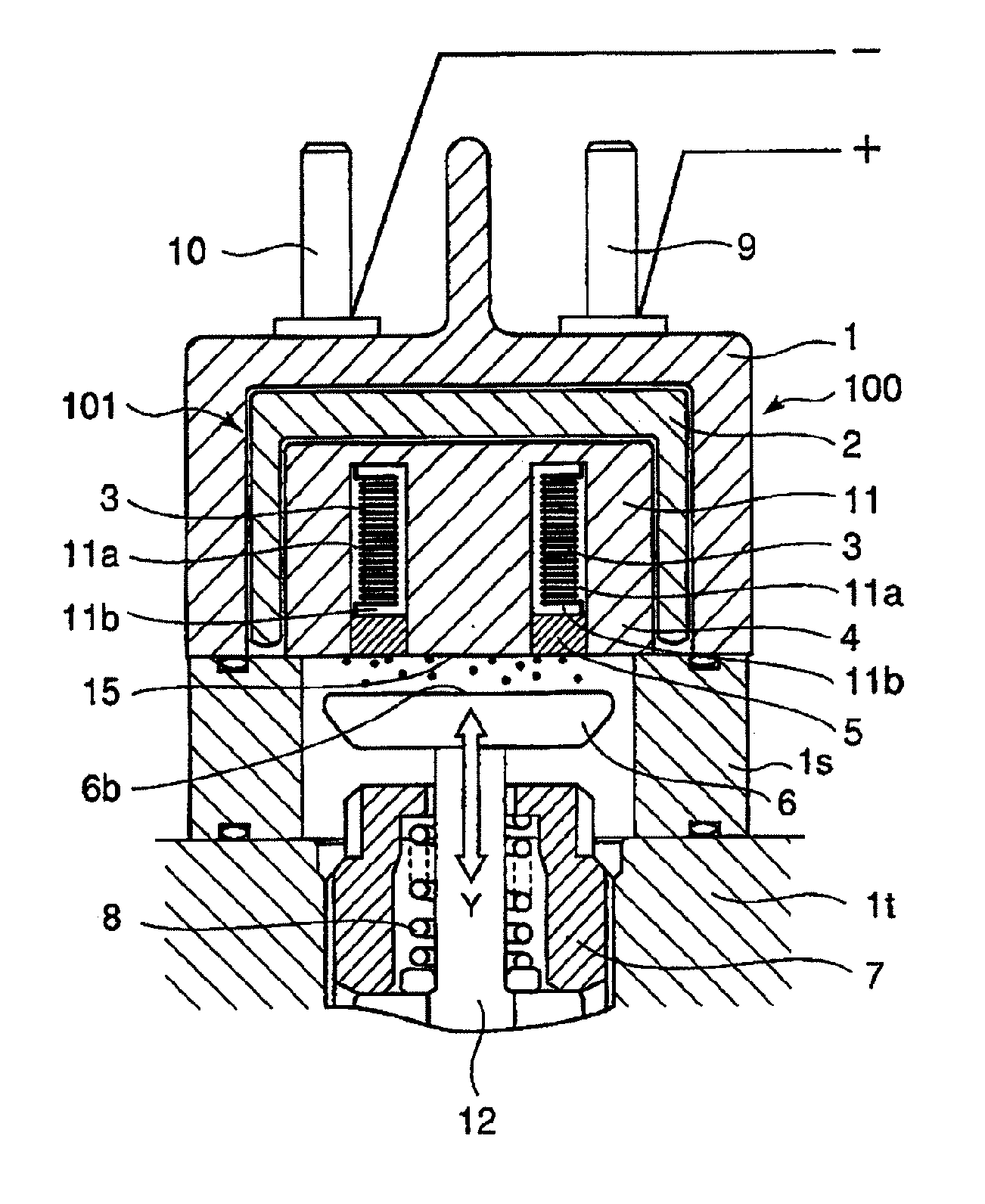
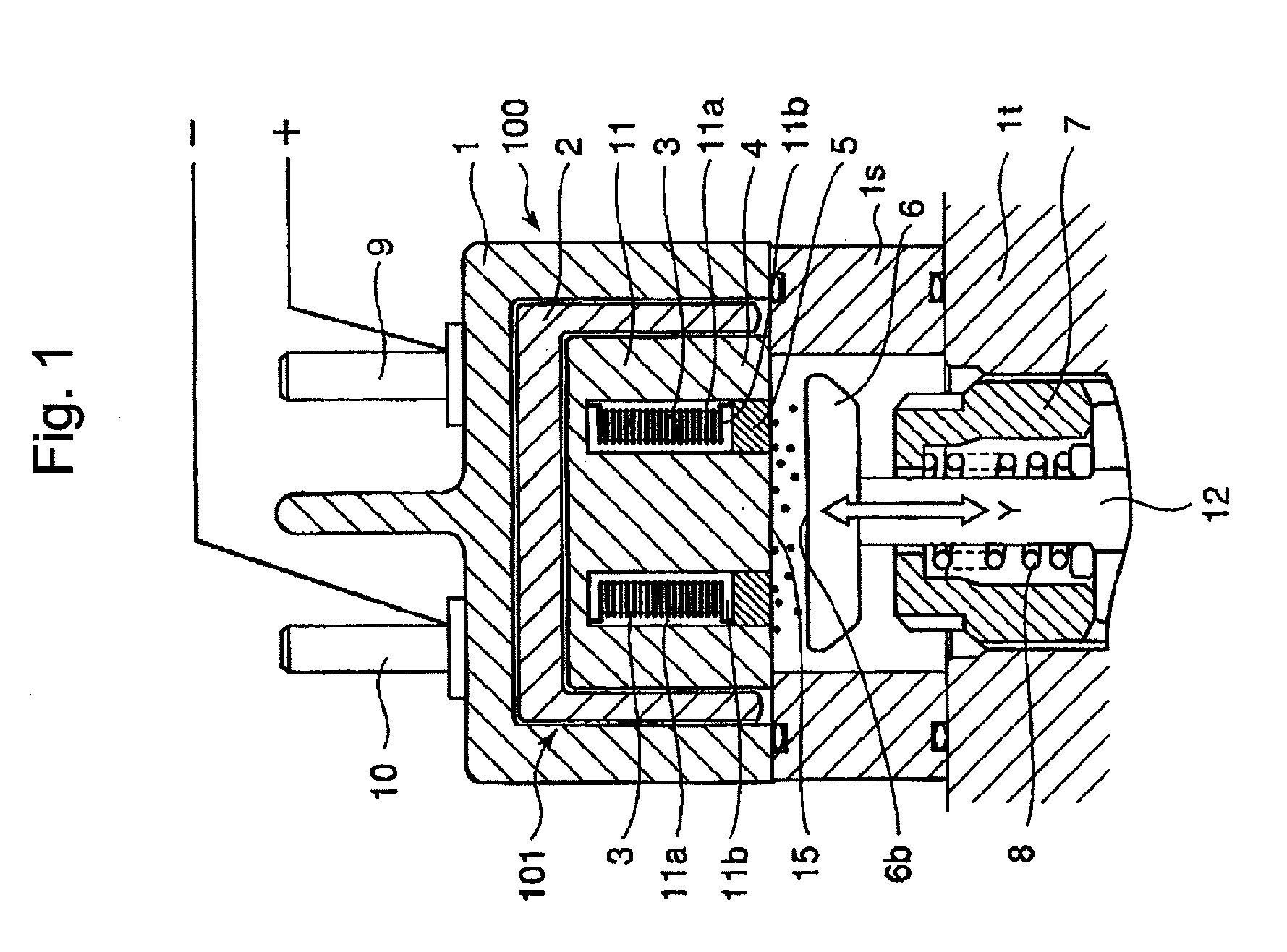
[0033]FIG. 1 shows a cross-section of a solenoid type electromagnetic valve according to an embodiment of the present invention. In FIG. 1, a solenoid device 100 comprises a plate-type armature 6 that is directly connected to an end part of a control valve (not shown) for opening and closing a fuel passage (not shown), as well as a solenoid core power supply body 101 that is provided with a solenoid core 11 integrated with a solenoidal coil 3 and housed in a solenoid case 2 of a box shape filled up with the fuel oil.

[0034]In the solenoid core power supply body 101, the solenoidal coil 3 is configured to be wound around a middle pr...


PUM


Abstract

Provided is a solenoid type electromagnetic valve having a high-speed responsivity and enhanced durability, thereby the valve can be protected from the erosion damage due to cavitations without losing the high-speed responsivity. The solenoid type electromagnetic valve is configured such that an attraction force arises between an attracting side face of a solenoid core power supply body and an attracted side face of an armature which is facing the attracting side face when a current is conducted through a solenoidal coil, while the attraction force is released between the attracting side face and the attracted side face when the current conducted through the solenoidal coil is cut off, wherein at least one plate member 5 of nonmagnetic material comprising nonmagnetic stainless steel, aluminum alloy or ceramic material is fitted to the attracting side face 15 of the solenoid core power supply body 101, and fluid insulation resin is filled therein, thereby the fluid insulation resin is solidified and secures the plate member 5 thereto.

Description

BACKGROUND OF THE INVENTION[0001]1. Field of the Invention[0002]The present invention relates to an erosion-protecting device for protecting a solenoid type electromagnetic valve from erosion thereof; the solenoid type electromagnetic valve is provided with a plate-type armature that is connected to an end part of a valve body which opens and closes a liquid passage (a fuel passage in a case of a fuel injection device), as well as, a solenoid core power supply body that is provided with a solenoidal coil integrated with the solenoid core in a solenoid case that is filled with the liquid.[0003]2. Background of the Invention[0004]A solenoid type electromagnetic configured such that a plate-type armature connected to an end part of a valve body which opens and closes a fuel passage and a solenoid core power supply body comprising a solenoidal coil integrated with the solenoid core in a solenoid case that is filled up with the fuel are provided, and an attracting side face of the soleno...

Claims


Application Information

Patent Timeline
Patent Type & Authority Applications(United States)
IPC IPC(8): F16K31/02
CPCF02M47/027F02M61/166F02M63/0019F02M2200/8046F02M2200/04H01F7/128F02M61/168F02M2200/02
Inventor OGAWA, HISAOTODA, MASAKIUEKI, TOSHIKAZU
Owner MITSUBISHI HEAVY IND ENGINE & TURBOCHARGER LTD
Why Eureka
Try Eureka