Internal self-check resistance bridge and method

a resistance bridge and self-checking technology, applied in the direction of resistance/reactance/impedence, reference comparison, resistance/reactance/impedence, etc., can solve the problems of linearity tests that require a substantial amount of time and technical expertise from the user, and it is difficult to precisely know the resistance of resistors during testing

Active Publication Date: 2011-01-06
JOHN FLUKE MFG CO INC
View PDF3 Cites 14 Cited by
  • Summary
  • Abstract
  • Description
  • Claims
  • Application Information

AI Technical Summary

Problems solved by technology

In general, it may be difficult to perform a linearity test because a user typically may be required to make complex electrical calculations and / or connect a variety of external resistors to the resistance bridge.
Thus, linearity tests require a substantial amount of time and technical expertise from the user.
For instance, it may be difficult to precisely know the resistances of the resistors during testing.
This all, however, adds to the complexity of conducting a linearity test because more calculations may be required and more resistors may be required to be connected and / or disconnected to the resistance bridge measurement circuit.
Therefore, calibrating or testing a resistance bridge measurement circuit requires a great deal of time and expertise from the user.

Method used


Image

  • Internal self-check resistance bridge and method
  • Internal self-check resistance bridge and method
  • Internal self-check resistance bridge and method

Examples


Embodiment Construction

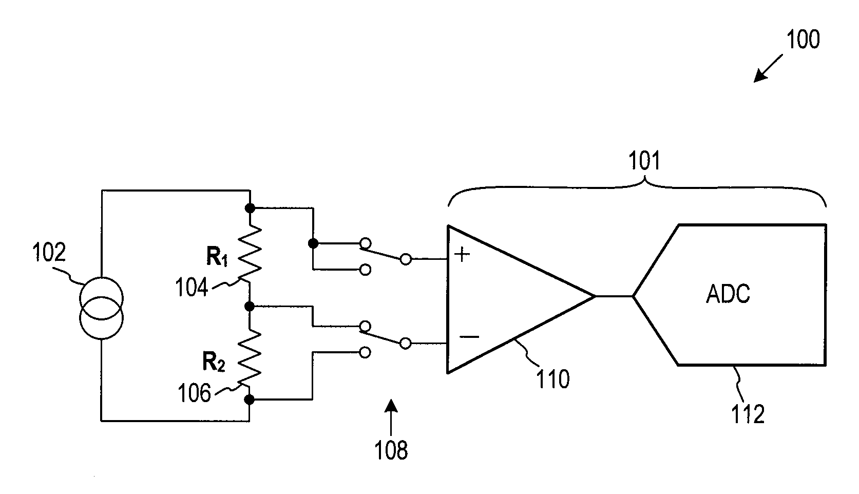
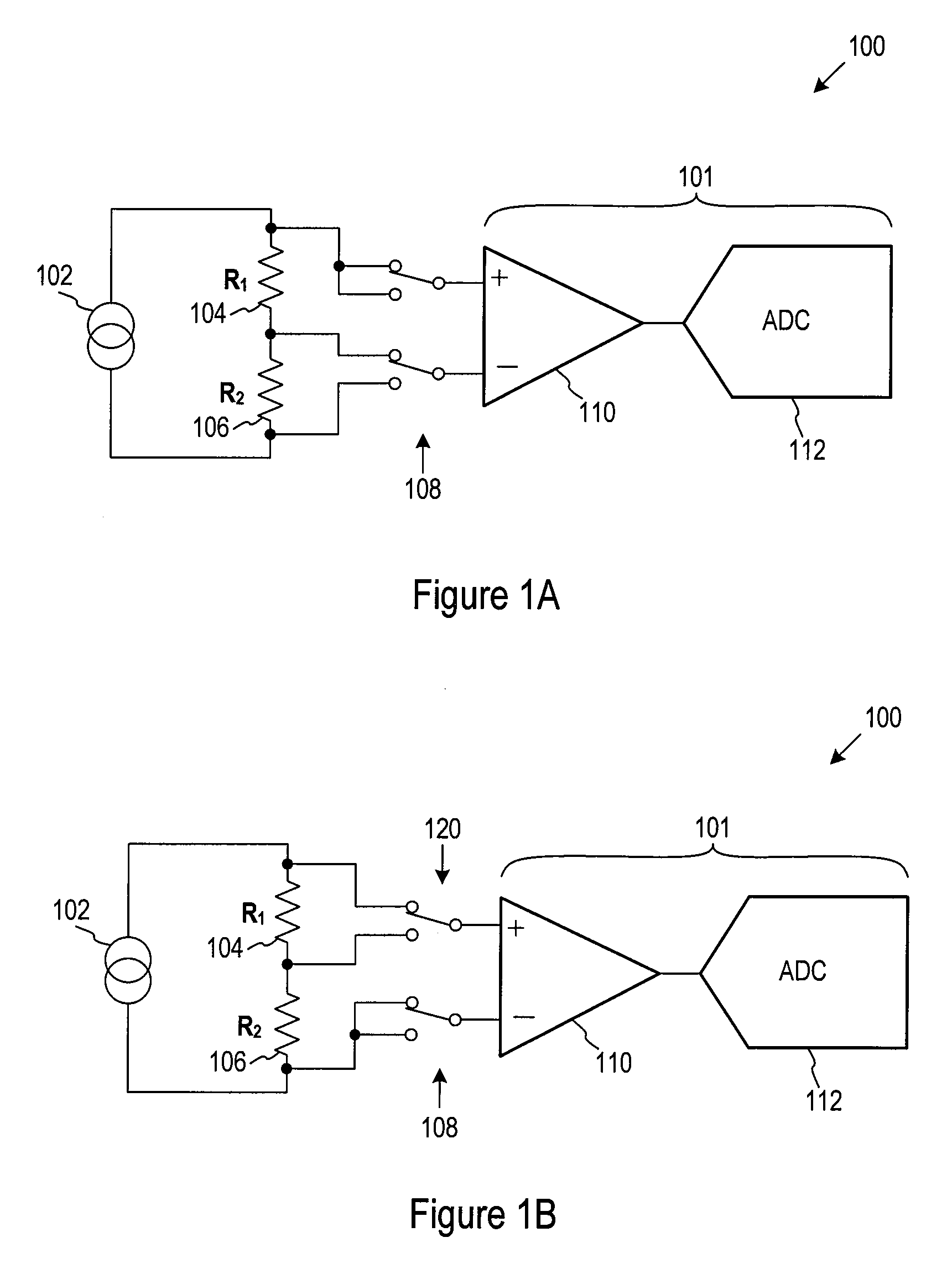
[0012]Embodiments of the present invention are directed toward a resistance bridge operable to perform an internal self-check and / or calibration. One or more embodiments utilize a resistance bridge measurement circuit comprising a network of resistors for performing an internal self-check test to calibrate and / or verify the accuracy of the resistance bridge measurement circuit. In one embodiment, the network of resistors are internal to the resistance bridge. The network of resistors may include any variety of combination of resistors and may be reconfigurable. The resistors may have similar resistances or different resistances. Some or all of the resistors may be coupled together, such as in series or in parallel or alternatively, may be configured to a first configuration and reconfigurable to a second configuration. The network of resistors may include any number of resistors. The resistance of the resistors may be known or unknown, or any combination thereof. The self-check test...


PUM


Abstract

One or more embodiments are directed to a resistance bridge measurement circuit configured to perform an internal self-check. The resistance bridge measurement circuit may include two or more internal resistors. In one embodiment, the resistance bridge measurement circuit may be configured to measure a first voltage across one of the resistors and a second voltage across a combination of the two resistors. The measured voltages may be converted to a resistance ratio and compared to an expected value. In another embodiment, the resistance bridge measurement circuit may be configured to measure a third voltage across the other of the two resistors and a fourth voltage across a combination of the two resistors. The measured voltages may be converted to corresponding resistance ratios, summed and compared to an expected value.

Description

TECHNICAL FIELD[0001]This invention is directed to resistance bridges, and more particularly one or more embodiments are directed to resistance bridge measurement circuits operable to perform an internal calibration and / or verification check.BACKGROUND OF THE INVENTION[0002]A resistance bridge is a device for comparing resistors by measuring and calculating a ratio between the resistors. For instance, a resistance bridge may be used to determine a resistance value of a first resistor that is electrically coupled to a second resistor. The resistance bridge measures electrical parameters of the two resistors, and, based on the electrical measurements, a microprocessor coupled to the resistance bridge calculates a resistance ratio of the two resistors. Resistance bridges may be used in a wide variety of applications that may use resistance measurements, such as thermometers, resistor calibrators, multimeters and the like. In general, resistance bridge measurement circuits provide high ...

Claims


Application Information

Patent Timeline
Patent Type & Authority Applications(United States)
IPC IPC(8): G01R27/08
CPCG01R27/02G01R17/105G01R35/00
Inventor WALKER, RICHARD W.
Owner JOHN FLUKE MFG CO INC
Why Eureka
Try Eureka