Microfluidic device

Active Publication Date: 2011-01-06
SONY CORP +1
View PDF55 Cites 47 Cited by
  • Summary
  • Abstract
  • Description
  • Claims
  • Application Information

AI Technical Summary

Benefits of technology

[0026]In another embodiment, a microfluidic device is disclosed, comprising a substrate, a microfluidic flow channel formed in said substrate, wherein said flow channel extends through a portion of said substrate adapted to facilitate cytometry analysis of cells flowing in said flow channel, said flow channel having an outlet, a sheath fluid flow channel formed in said substrate and fluidically coupled to said microfluidic flow channel, and a collection bag having a first chamber and a second chamber, said first chamber being fluidically coupled to said microfluidic flow channel outlet and said second chamber being fluidically coupled to said

Problems solved by technology

Droplet cell sorters, however, are not particularly biosafe.
Unfortunately, this type of system does not lend itself to the sterility and operator protection required for rou

Method used


Image

  • Microfluidic device
  • Microfluidic device
  • Microfluidic device

Examples


Embodiment Construction

[0043]For the purposes of promoting an understanding of the principles of the disclosure, reference will now be made to the embodiments illustrated in the drawings and specific language will be used to describe the same. It will nevertheless be understood that no limitation of the scope of the disclosure is thereby intended, such alterations and further modifications in the illustrated device, and such further applications of the principles of the disclosure as illustrated therein are contemplated as would normally occur to one skilled in the art to which the disclosure relates.

Microfluidic Device Having Onboard Sterilization Capability

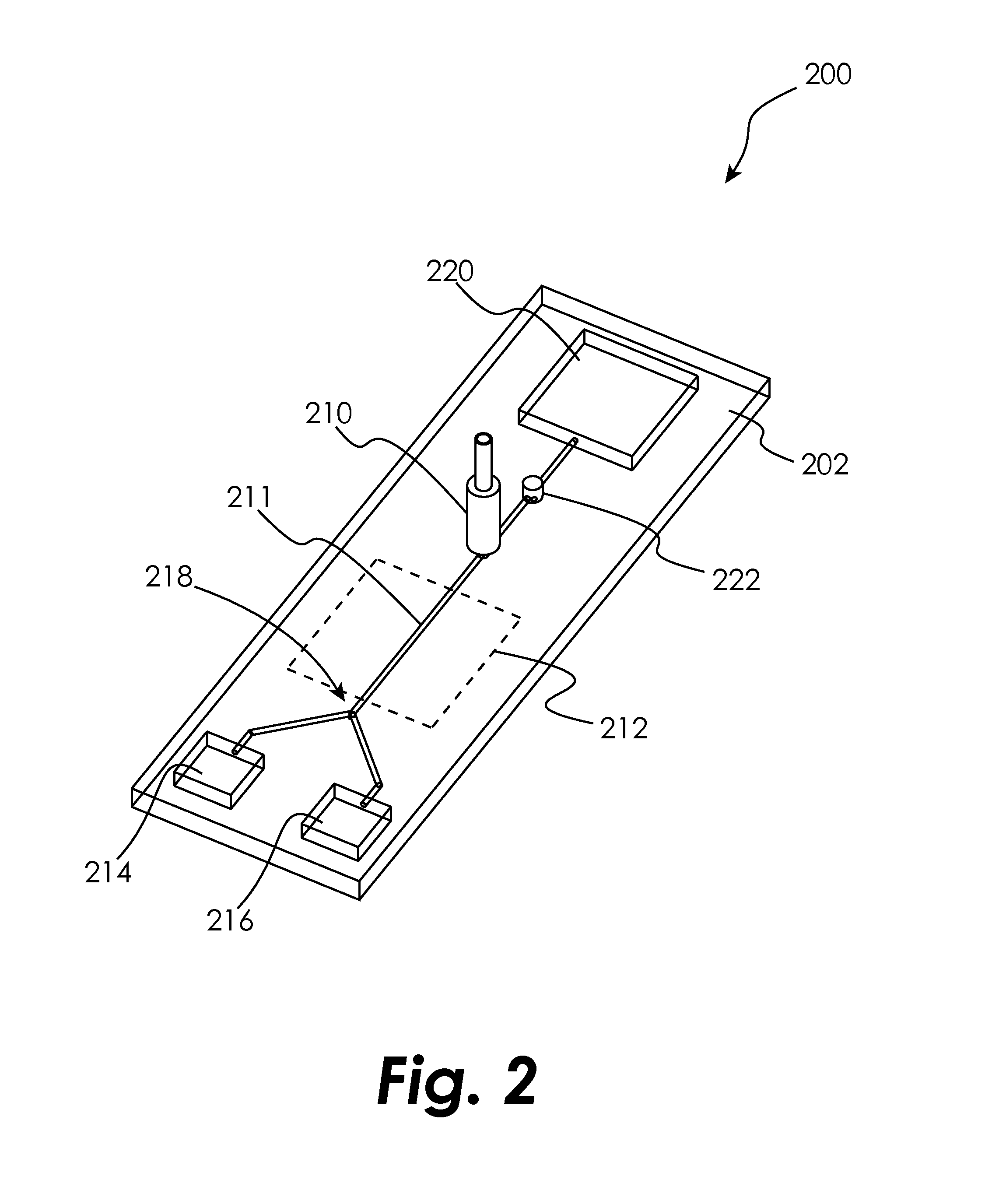
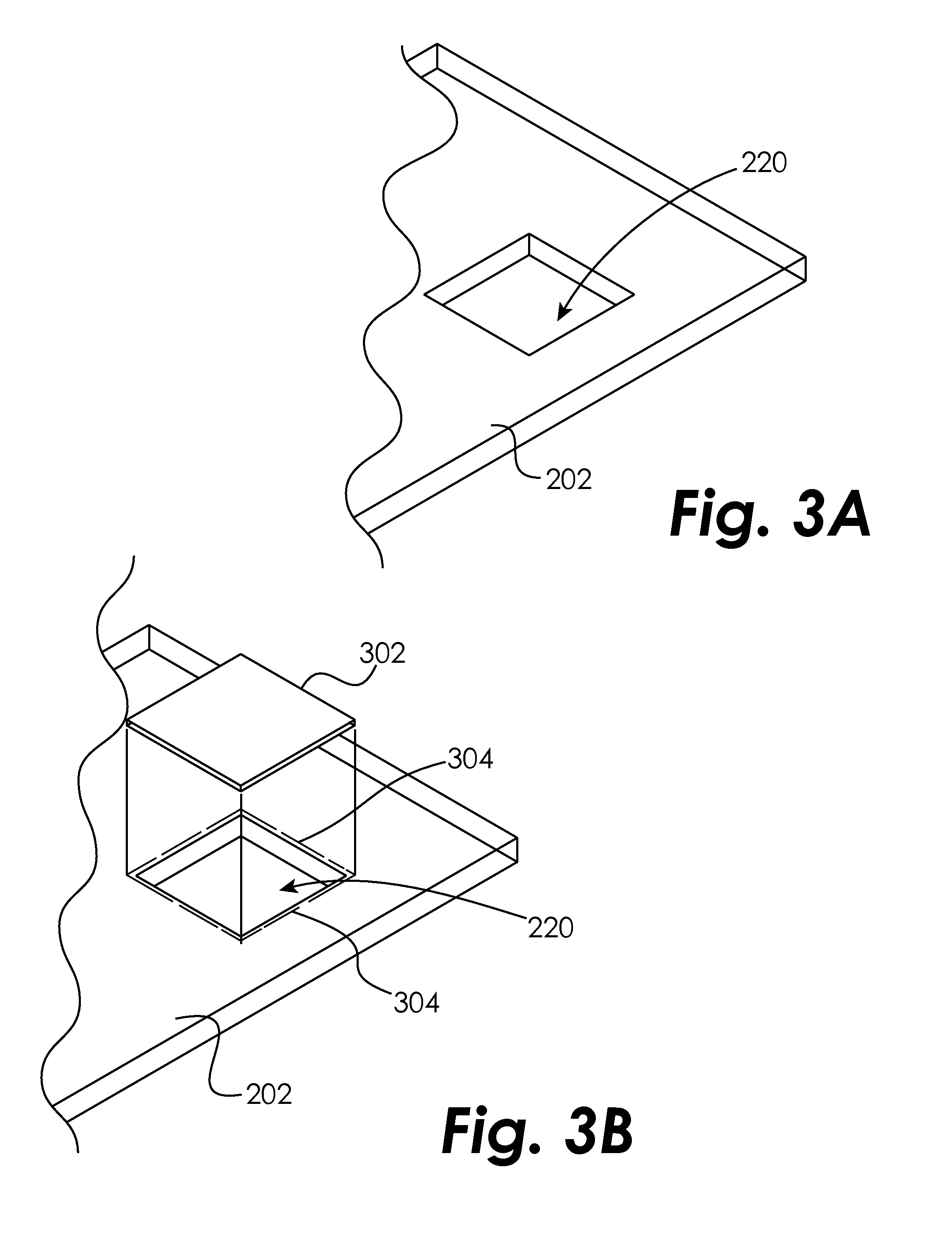
[0044]Certain embodiments of the present disclosure are generally directed to integral sterilization capabilities on a microfluidic device, such as a cytometry chip, to sterilize the device after the cell sample undergoes the cytometry analysis. The cytometry analysis may be a flow cytometry analysis, as described above, or an image cytometry analysis...


PUM


Abstract

The present disclosure relates to microfluidic devices adapted for facilitating cytometry analysis of particles flowing therethrough. In certain embodiments, the microfluidic devices have onboard sterilization capabilities. In other embodiments, microfluidic devices have integral collection bags and methods for keeping the microfluidic channels clean.

Description

CROSS-REFERENCE TO RELATED APPLICATIONS[0001]The present application claims the benefit of the following: U.S. Provisional Patent Application No. 61 / 223,089, which was filed Jul. 6, 2009, U.S. Provisional Patent Application No. 61 / 223,090, which was filed Jul. 6, 2009, U.S. Provisional Patent Application No. 61 / 223,091, which was filed Jul. 6, 2009, U.S. Provisional Patent Application No. 61 / 223,399, which was filed Jul. 7, 2009, U.S. Provisional Patent Application No. 61 / 223,400, which was filed Jul. 7, 2009, U.S. Provisional Patent Application No. 61 / 223,401, which was filed Jul. 7, 2009, U.S. Provisional Patent Application No. 61 / 223,094, which was filed Jul. 6, 2009, U.S. Provisional Patent Application No. 61 / 223,402, which was filed Jul. 7, 2009, U.S. Provisional Patent Application No. 61 / 223,404, which was filed Jul. 7, 2009, all of which are hereby incorporated herein by reference in their entireties.TECHNICAL FIELD OF THE DISCLOSURE[0002]The present disclosure relates to mic...

Claims


Application Information

Patent Timeline
IPC IPC(8): C12Q1/02C12M1/34
CPCG01N2015/149B01L2300/0864B01L3/5027B01L2300/0816G01N15/1484B01L2300/0681B01L2400/0436B01L2200/147B01L2400/0475B01L2200/0647Y10T436/25
Inventor DURACK, GARY P.
Owner SONY CORP
Why Eureka
Try Eureka