Low duty mode for femtocell base stations

a low duty mode and base station technology, applied in power management, wireless commuication services, high-level techniques, etc., can solve the problem of affecting the amount of overlay macro bs's that may still exis

Inactive Publication Date: 2011-01-06
INTEL CORP
View PDF2 Cites 37 Cited by
  • Summary
  • Abstract
  • Description
  • Claims
  • Application Information

AI Technical Summary

Problems solved by technology

For practical reasons, however, some amount of ...

Method used


Image

  • Low duty mode for femtocell base stations
  • Low duty mode for femtocell base stations
  • Low duty mode for femtocell base stations

Examples


Embodiment Construction

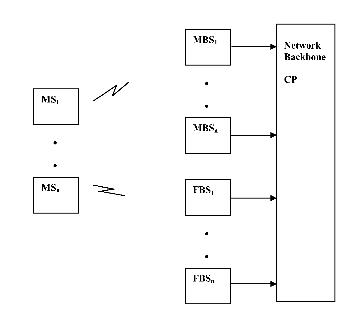
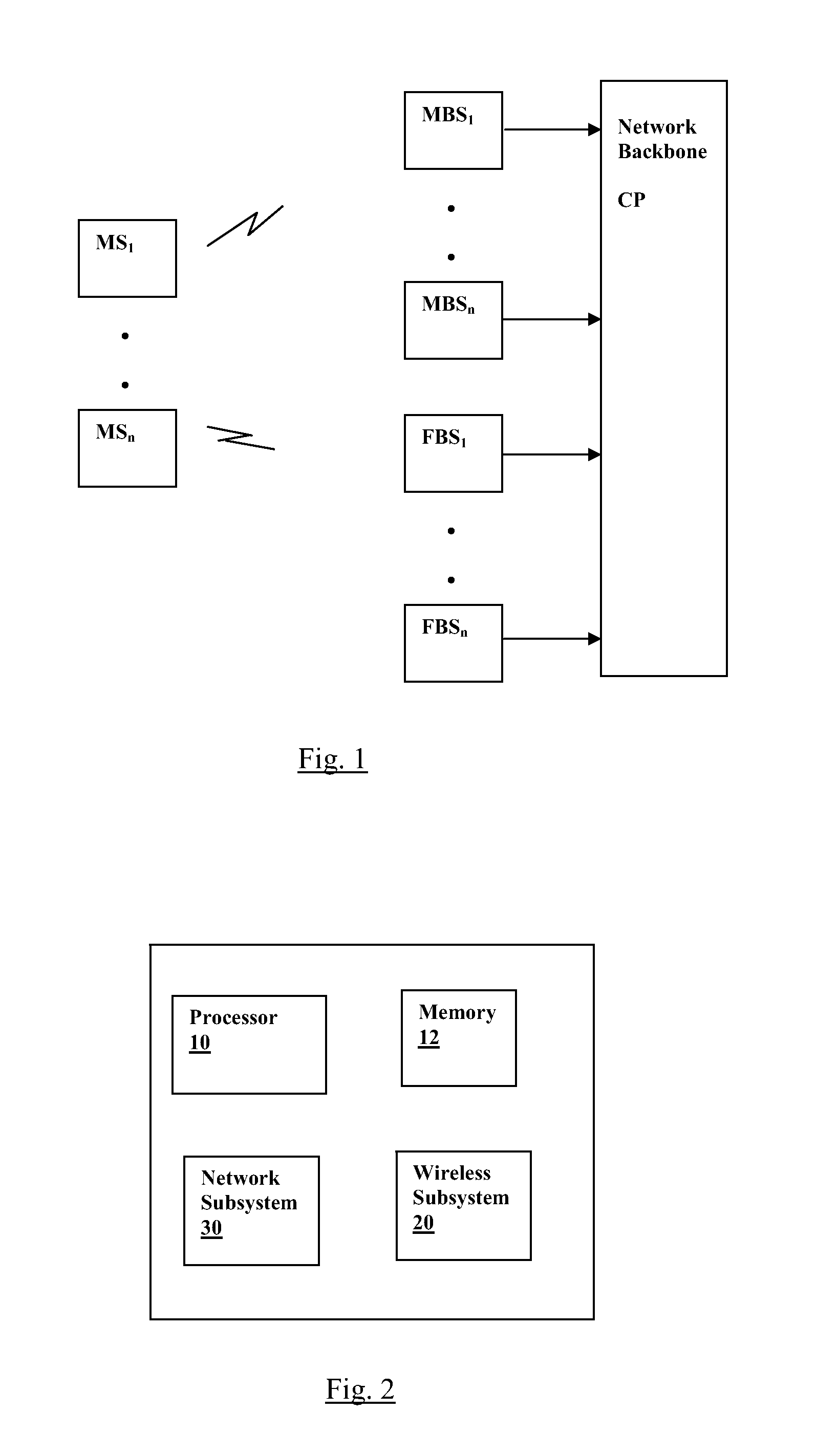
[0012]FIG. 1 illustrates the basic components of a cellular wireless communications system that includes femtocells and macro cells. A plurality of macro cell base stations MBS1 through MBSn and femtocell base stations FBS1 through FBSn are shown, where each base station is located to cover a specific geographic area or cell. A plurality of mobile stations MS1 through MSn are shown that communicate wirelessly with one or more of the base stations. The base stations interface via a backhaul link to the core portion CP (backbone) of the service provider's network over which they may relay traffic as well as communicate with one another.

[0013]FIG. 2 shows the subsystem components of an exemplary base station. A processing device 10 coupled to an associated memory 12 controls the operation of a wireless subsystem 20 for providing the air interface and a network subsystem 30 for interfacing to the backhaul link. An exemplary mobile station would be represented similarly minus the network...


PUM


Abstract

A low duty mode is provided for a femtocell base station operating as part of a cellular communications system. Methods and systems are described for reducing the service impact of the low-duty mode on mobile stations that are either already attached or are attempting to attach to a femtocell base station.

Description

[0001]This application claims the benefit of priority to U.S. Provisional Patent Application Ser. No. 61 / 223,360, filed on Jul. 6, 2009, which is incorporated herein by reference in its entirety.BACKGROUND[0002]Cellular wireless communications systems such as those defined by the IEEE 802.16 standard (IEEE std. 802.16-2004, approved Jun. 24, 2004) provide communications for mobile systems (MS) (e.g., phones, computers, or other portable devices) over a service provider's core network or backbone by means of base stations (BS) connected to the core network that relay communications to and from the MS via a wireless link The geographic area over which a particular BS is able to communicate wirelessly (i.e., the air interface) is referred to as a cell. An MS enters the network by attaching to a specific BS with which it is in range, and the attachment may move to other BS's when conditions warrant (e.g., a change of location as the MS moves from one cell to another) with a handover pro...

Claims


Application Information

Patent Timeline
IPC IPC(8): H04W4/00
CPCH04L12/66H04W36/0083H04W36/04H04W52/0206H04W52/146H04W84/045H04W52/10H04W36/0085Y02D30/70H04W36/00837H04W48/16H04W52/02
Inventor VENKATACHALAM, MUTHAIAHYANG, XIANGYING
Owner INTEL CORP
Why Eureka
Try Eureka