
Virtual appliance deploying system

a virtual appliance and deployment system technology, applied in the field of virtual appliance deployment systems, can solve the problem that the operation of changing settings cannot be automatically performed for different software used

Inactive Publication Date: 2011-01-06
NEC CORP
View PDF3 Cites 161 Cited by
  • Summary
  • Abstract
  • Description
  • Claims
  • Application Information

AI Technical Summary

Benefits of technology

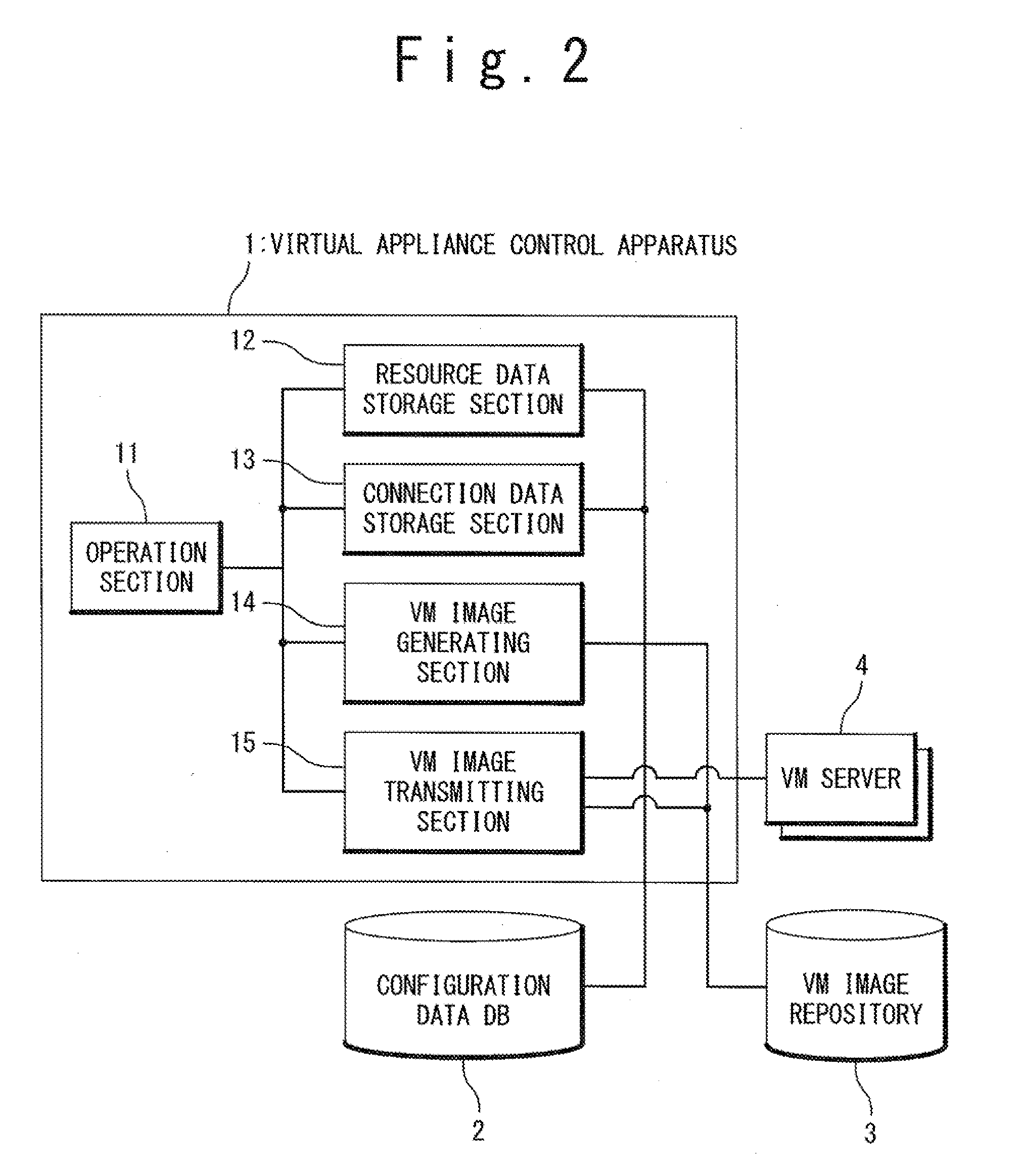
[0018]Prior to deployment of a VA instance, the virtual appliance control apparatus stores resource data to be assigned to the VA instance to be deployed and connection data indicating a connecting relation among the VA instances in the configuration data DB by using a resource data storing section and a connection data storing section. Moreover, in deploying a VA instance, the virtual appliance control apparatus uses the VM image generating section to generate a VM image including a setting file depending on physical configuration and the connecting relation among the VA instances, from the VM image template in the VM image repository and the resource data and the connection data stored in the configuration data DB.

Problems solved by technology

Here, regarding the virtual appliance deploying system according to the technique described in the above document, there can be problems as follows.
A first problem is in that, in order to automate a setting operation depending on application software operating on a virtual appliance, it is required to prepare a different setting program for each type of application.
A second problem is in that an operation of changing settings cannot be automatically performed for different software used in combination with the virtual appliance to be deployed.

Method used


Image

  • Virtual appliance deploying system
  • Virtual appliance deploying system
  • Virtual appliance deploying system

Examples


Embodiment Construction

[0042]Hereinafter, a virtual appliance deploying system according to the present invention will be described with reference to the attached drawings.

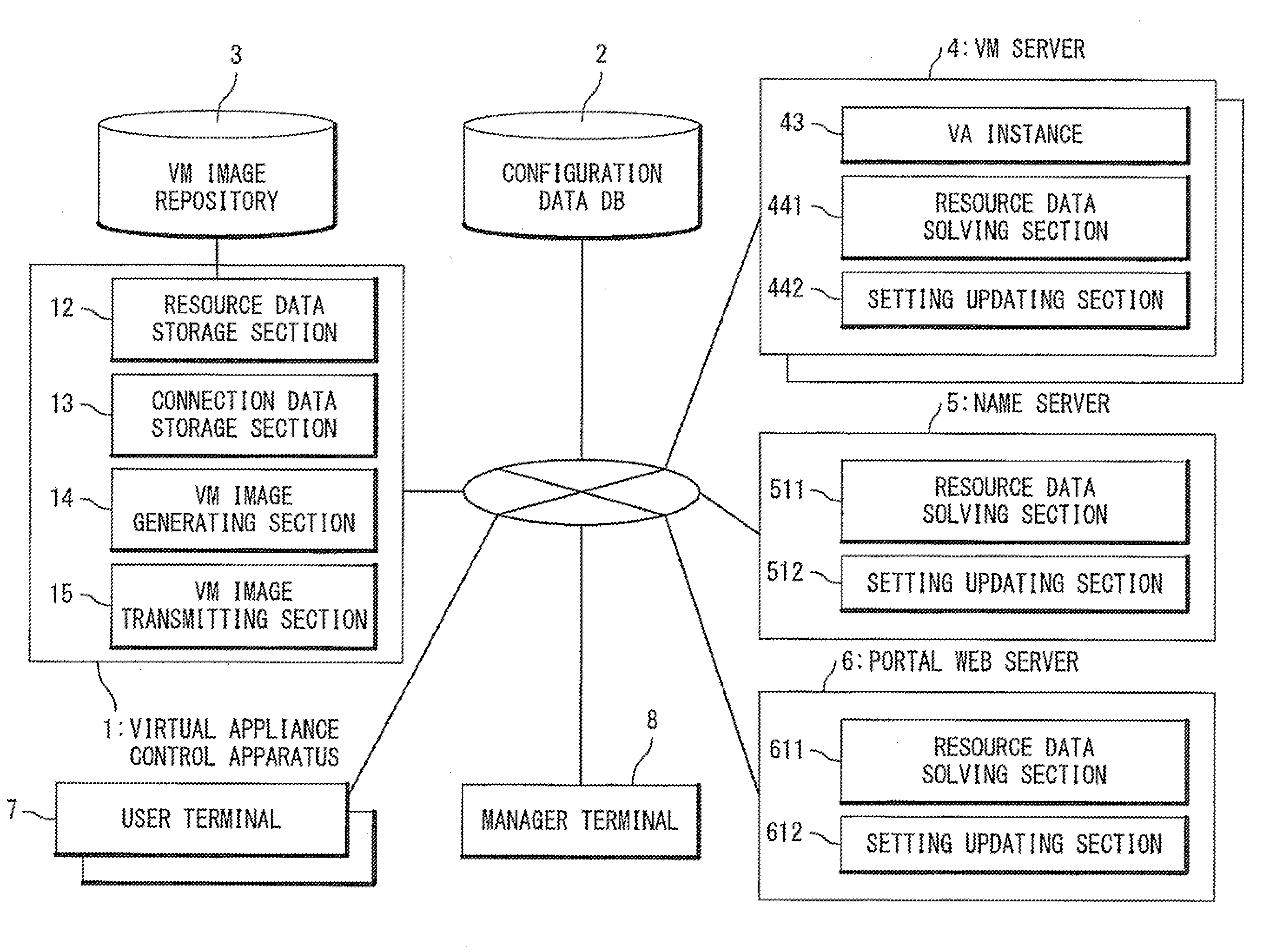
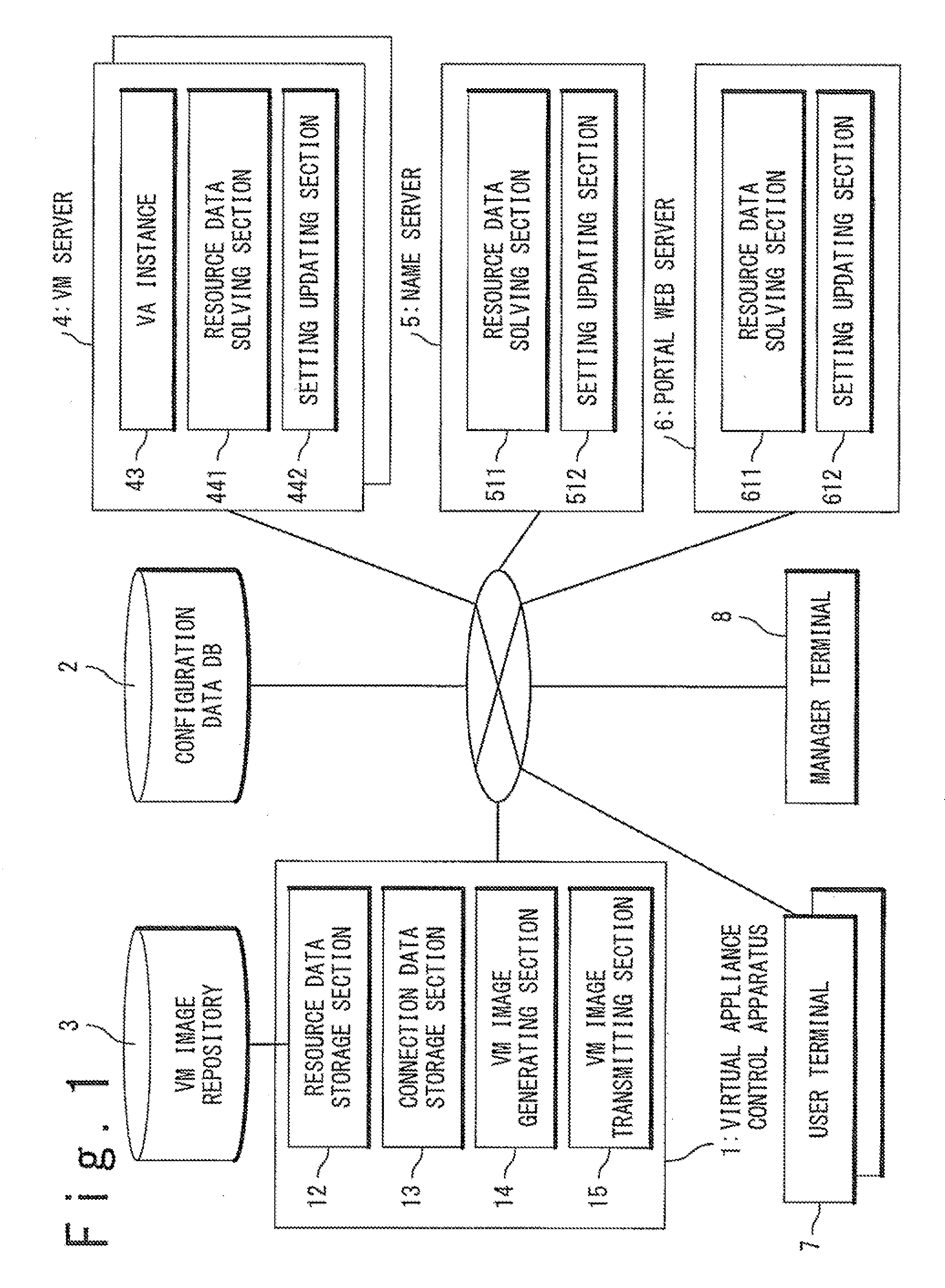
[0043]Referring to FIG. 1, the virtual appliance deploying system according to an exemplary embodiment of the present invention includes a virtual appliance control apparatus 1, a configuration data DB (database) 2, a VM (virtual machine) image repository 3, VM servers 4, a name server 5, a portal Web server 6, user terminals 7, and an manager terminal 8.

[0044]Among these units, the units (the virtual appliance control apparatus 1, the configuration data DB 2, the VM servers 4, the name server 5, the portal Web server 6, the user terminals 7, and the manager terminal 8) other than the VM image repository 3 are connected to each other through a network. The VM servers 4, the name server 5, and the portal Web server 6 are server apparatuses. Also, the VM servers 4 each have a function of operating one or more VMs. Moreover, the user termi...


PUM


Abstract

In deployment of a virtual appliance to a physical server, a setting file required for the virtual appliance to operate is automatically generated based on a configuration of the physical server and a network configuration, and connection relation between the virtual appliances. Specifically, resource data assigned to the virtual appliance and connection data are registered on a configuration data database, and a template of the setting file is set in advance to a virtual machine image for the virtual appliance. In the deployment of the virtual appliance to the physical server, optional attributes described in the template of the setting file are replaced by specific setting values (actual data) by using the resource data and the connection data stored in the configuration data database, to generate the setting file.

Description

TECHNICAL FIELD[0001]The present invention relates to virtual appliance deploying systems, and in particular, to a virtual appliance deploying system of setting a connecting relation among a plurality of virtual appliances and a connecting relation between the virtual appliance and a peripheral service.BACKGROUND ART[0002]An example of the virtual appliance deploying system has been described in a document of “Virtual Appliances for Deploying and Maintaining Software” (Proceedings of the 17th Large Installation Systems Administration Conference, 2003) written by Constantine Sapuntzakis, David Brumley, Ramesh Chandra, Nickolai Zeldovich, Jim Chow, Monica S. Lam, and Mendel Rosenblum.[0003]In the technique described in the above Non-Patent Literature, a system of deploying virtual appliances (VAs) is proposed as means of reducing time and effort on introducing and maintaining software. The appliance means a device provided as a combination of a hardware unit and a software unit operat...

Claims


Application Information

Patent Timeline
Patent Type & Authority Applications(United States)
IPC IPC(8): G06F15/177G06F9/455
CPCG06F9/5044G06F9/5077G06F2009/45562G06F9/45558G06F8/63
Inventor KAWATO, MASAHIRO
Owner NEC CORP
Learn More