
Integrated circuit device and method for determining an index of an extreme value within an array of values

an array value and index technology, applied in the field of integrated circuit devices and methods for determining extreme values within array values, can solve the problems of reducing the efficiency of the dsp for performing such operations, and affecting the overall performance of the dsp

Inactive Publication Date: 2015-10-20
NXP USA INC
View PDF9 Cites 380 Cited by
  • Summary
  • Abstract
  • Description
  • Claims
  • Application Information

AI Technical Summary

Benefits of technology

This approach enhances DSP efficiency by eliminating the need for 'if' statements, allowing multiple index operations per cycle and fully exploiting pipelined architecture benefits, thereby improving overall DSP performance in finding indices of extreme values within arrays.

Problems solved by technology

Digital Signal Processor (DSP) applications are becoming increasingly more demanding in their requirements of DSP cores.
However, a change of flow, such as may result from the use of an ‘if’ statement, effectively voids any benefit provided by such a pipelined architecture for that part of the application program code, significantly reducing the efficiency of the DSP.
In addition, the use of an ‘if’ statement to perform such max / min value index finding operations prevents more than one max / min value index finding operation being performed per cycle (due to the limitation of using a dedicated conditional flag within the DSP), irrespective of the ability of the processing parallelism within DSP architecture.
Since such max / min value index finding operations may be required to be performed on a regular basis within a mobile telecommunication receiver, such a reduction in the efficiency of the DSP for performing such operations can have a significant detrimental effect on the overall performance of the DSP.

Method used


Image

  • Integrated circuit device and method for determining an index of an extreme value within an array of values
  • Integrated circuit device and method for determining an index of an extreme value within an array of values
  • Integrated circuit device and method for determining an index of an extreme value within an array of values

Examples


Embodiment Construction

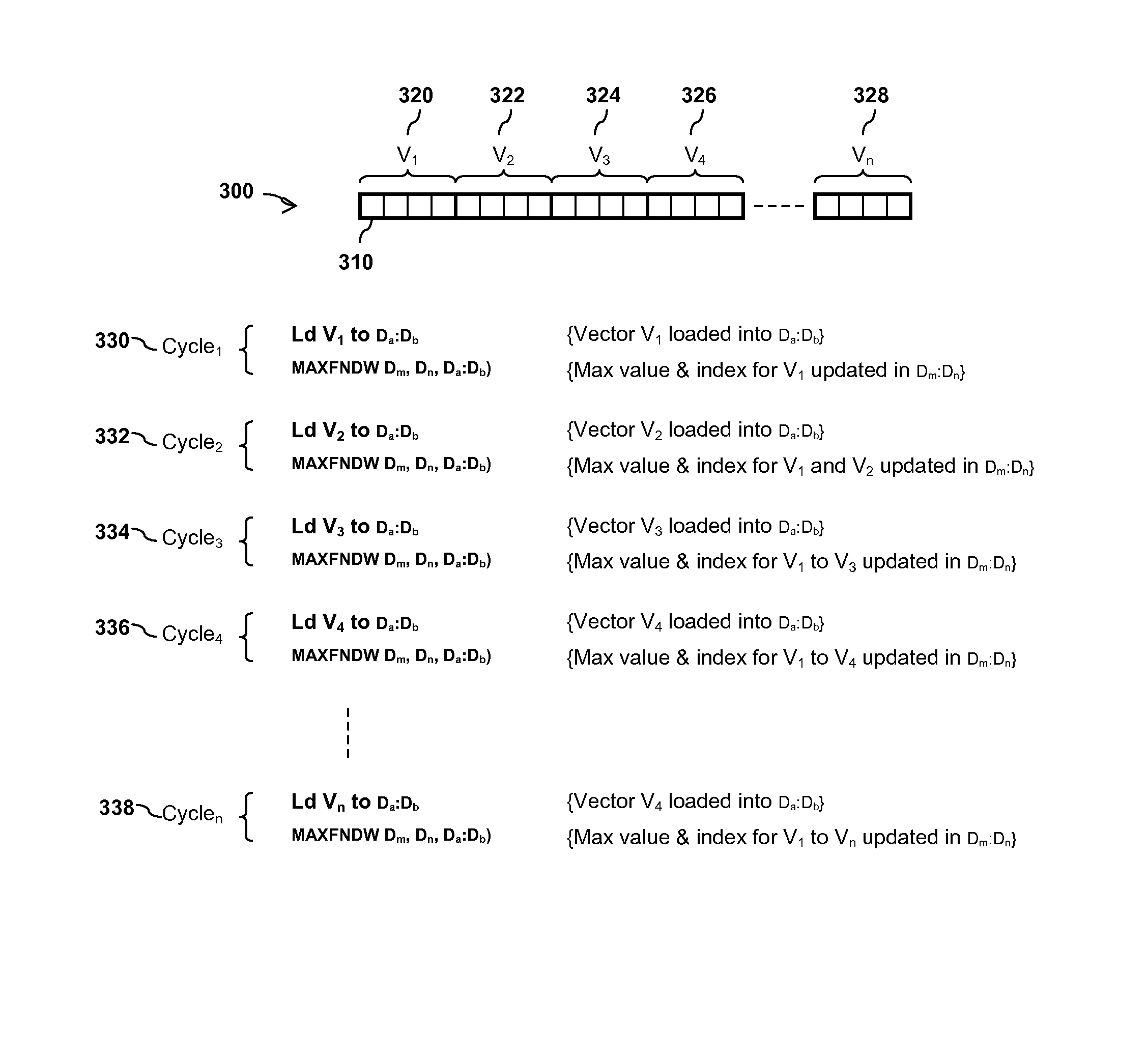
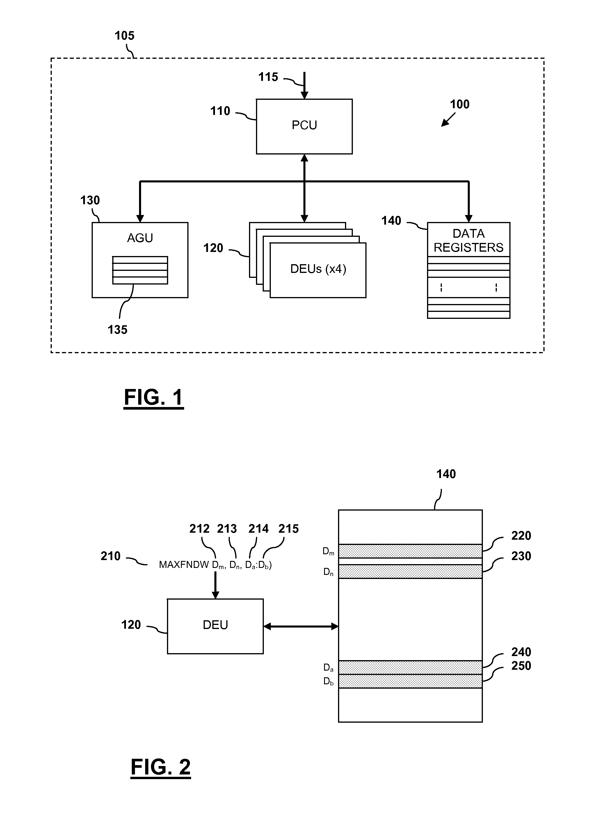
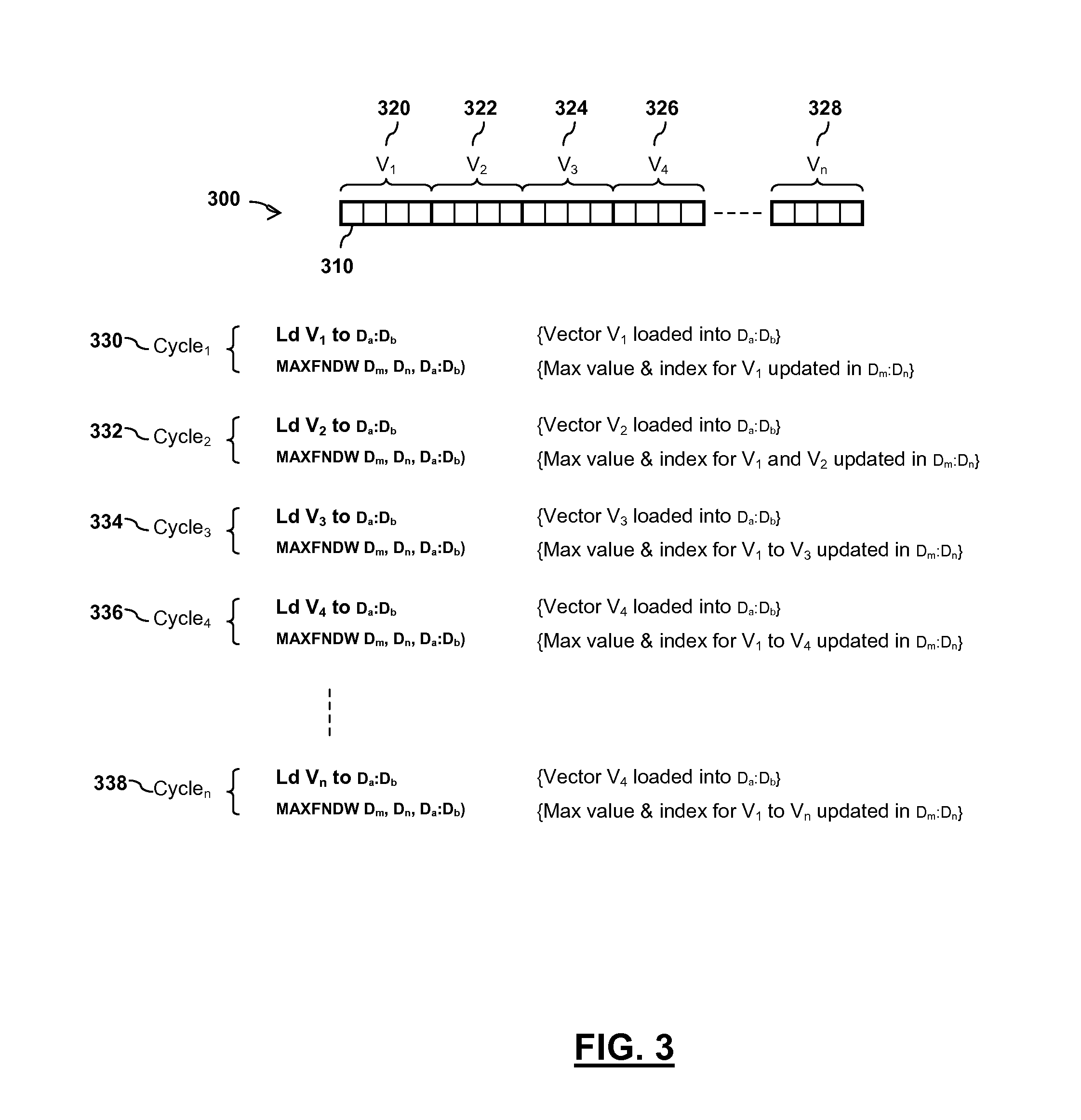
[0014]Examples of the present invention will now be described with reference to an example of a digital signal processor (DSP) architecture. However, it will be appreciated that the present invention is not limited to the specific DSP architecture herein described with reference to the accompanying drawings, and may equally be applied to alternative DSP architectures. For the illustrated example, a DSP architecture is provided comprising separate data and address registers. Alternatively, the address registers may be combined with the data registers, and the combined registers being used to provide address storage, etc. Furthermore, for the illustrated examples, the DSP architecture is shown as comprising four data execution units. However, it will be appreciated that examples of the present invention may equally be implemented within a DSP architecture comprising any other number of data execution units, e.g. one, two, eight, etc. Additionally, because the illustrated example embod...


PUM


Abstract

An integrated circuit device comprises at least one digital signal processor, DSP, module, the at least one DSP module comprising a plurality of data registers and at least one data execution unit, DEU, module arranged to execute operations on data stored within the data registers. The at least one DEU module is arranged to, in response to receiving an extreme value index instruction, compare a previous extreme value located within a first data register set of the DSP module with at least one input vector data value located within a second data register set of the DSP module, and determine an extreme value thereof. The at least one DEU module is further arranged to, if the determined extreme value comprises an input vector data value located within the second data register set, store the determined extreme value in the first data register set, determine an index value for the determined extreme value, and store the determined index value in the first data register set.

Description

FIELD OF THE INVENTION[0001]The field of this invention relates to an integrated circuit device and method for determining an index of an extreme value within an array of values.BACKGROUND OF THE INVENTION[0002]Digital Signal Processor (DSP) applications are becoming increasingly more demanding in their requirements of DSP cores. For example, the increased data rates specified for the fourth generation (4G) of mobile telecommunication systems require significantly higher DSP performance. One operation that is often required to be performed is that of finding the index of an element comprising, say, a maximum or minimum value, or modulus (absolute maximum) value, within a given systematic arrangement of values such as an array (as opposed to the maximum / minimum value itself). For clarity, an index comprises an identifier for a specific element within, say, an array, such as in the form of a relative location of the array element within the array. For example, the search for the index...

Claims


Application Information

Patent Timeline
Patent Type & Authority Patents(United States)
IPC IPC(8): G06F9/30G06F17/30
CPCG06F9/30021G06F17/30336G06F9/30036G06F16/2272
Inventor MOSKOVICH, ILIAAMIR, AVIRAMBARAK, ITZHAKBEN ZEEV, ELIEZER
Owner NXP USA INC
Learn More