Electronic pen and electronic pen system

a pen and electronic technology, applied in the field of electronic pen and electronic pen system, can solve the problems of difficult for users to view the display, impossible for users to recognize the color, width, etc. of lines when the pen is off, etc., and achieve the effect of easy recognition of the pen property

Inactive Publication Date: 2011-01-13
PANASONIC CORP
View PDF5 Cites 83 Cited by
  • Summary
  • Abstract
  • Description
  • Claims
  • Application Information

AI Technical Summary

Benefits of technology

[0012]In order to address the problems above, one aspect of the present embodiments provides an electronic pen electronically drawing lines on a terminal apparatus, the electronic pen comprising: a display that displays a property of the electronic pen, the display being a piece of electronic paper and extending around an external periphery of the electronic pen; a gap that is provided between both opposing ends of the display; and a conductive member that is positioned in the gap and is connected to the display to supply signals to the display.
[0013]Another aspect of the present embodiments provide an electronic pen system comprising: an electronic pen and a terminal apparatus on which the electronic pen electronically draws lines, wherein, the electronic pen comprises: a display that displays a property of the electronic pen, the display being a piece of electronic paper and extending around

Problems solved by technology

So the display area is small, which makes it difficult for the user to view the display.
Further, when the electronic pen is turned of

Method used


Image

  • Electronic pen and electronic pen system
  • Electronic pen and electronic pen system
  • Electronic pen and electronic pen system

Examples


first embodiment

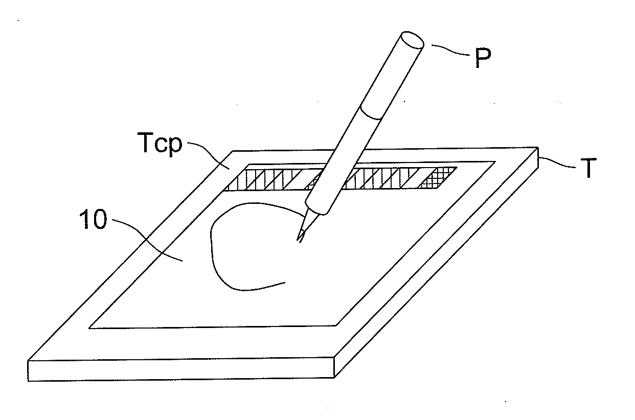
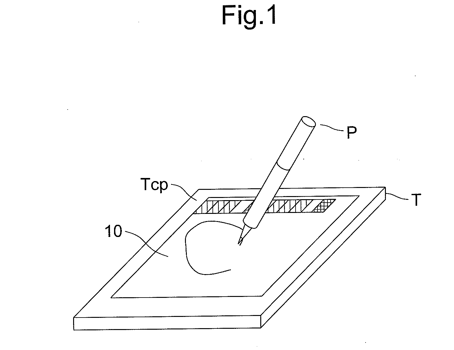
[0035]FIGS. 1 though 6 are used to illustrate the first embodiment of the present invention. FIG. 1 is a schematic view of a system according to the first embodiment of the present invention. An electronic pen system is configured with an electronic pen P and a terminal apparatus T, and a user electronically draws lines on a display 10 of the terminal apparatus T with the electronic pen P. The display 10 of the terminal apparatus T displays a color palette Tcp as a menu to set up a line density.

[0036]In the first embodiment, examples are given only to specify density (i.e. gray scale) as a pen property. However, other pen property settings such as color, line width, line type (e.g., solid, broken, double lines) and the like may be included in the menu to be displayed together on the display 10 of the terminal in the similar manner. The line written by the electronic pen P appears on the display 10 with the set pen property.

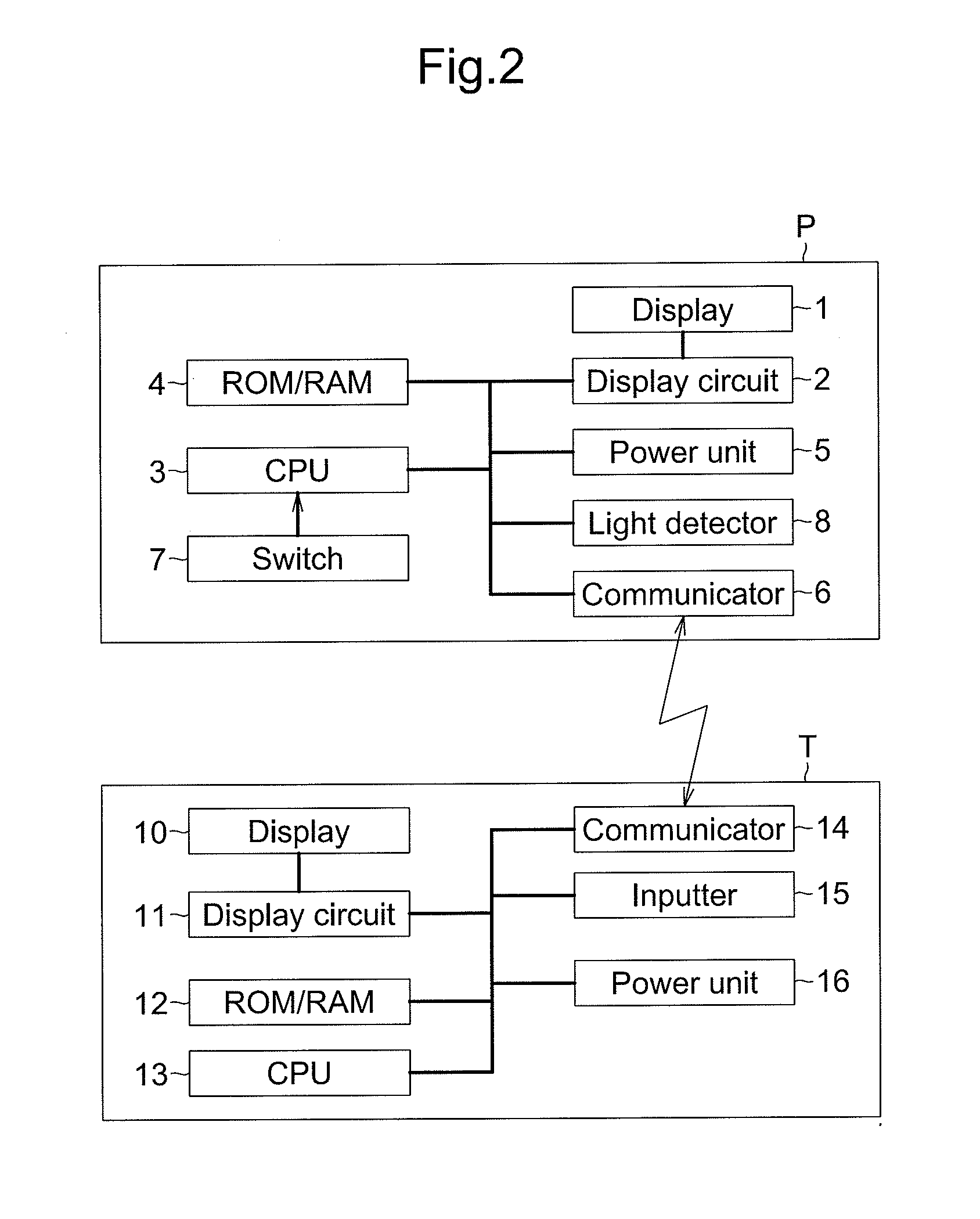
[0037]FIG. 2 is a basic block diagram of the electronic pen ...

second embodiment

[0081]FIGS. 7A, 7B, 8A, and 8B are used to illustrate a second embodiment of the present invention. FIGS. 7A and 7B illustrate a basic configuration of an electronic pen according to the second embodiment of the present invention. FIGS. 8A and 8B are cross sectional views of a display of the electronic pen according to the second embodiment of the present invention. The basic block diagram of the second embodiment is the same as the first embodiment, which is shown in FIG. 2. Structural elements similar to the first embodiment are provided with the identical numerical references, and illustrations thereof are omitted.

[0082]FIGS. 7A and 7B illustrate the display 1 of the electronic pen according to the second embodiment of the present invention. FIG. 8A is a cross sectional view of the display 1 of according to the second embodiment of the present invention, taken along a broken line X5-X6 (of FIG. 7B), while FIG. 8B is fragmentary view of an arrowed portion Y1 (of FIG. 7B).

[0083]In ...

third embodiment

[0110]FIGS. 10A, 10B, 11A and 11B are used to illustrate a third embodiment of the present invention. FIGS. 10A and 10B illustrate a basic configuration of an electronic pen according to the third embodiment of the present invention. FIGS. 11A and 11B are cross sectional views of a display of the electronic pen according to the third embodiment of the present invention. The basic block diagram of the third embodiment is the same as the first embodiment, which is shown in FIG. 2. In FIGS. 10A and 10B, structural elements similar to the first and the second embodiments are provided with the identical numerical references, and illustrations thereof are omitted.

[0111]FIGS. 10A and 10B illustrate the display 1 according to the third embodiment of the present invention. FIG. 11A is a cross sectional view of the display 1, taken along a broken line X7-X8 (of FIG. 10B), while FIG. 11B is fragmentary view of an arrowed portion Y2 (of FIG. 10B).

[0112]In FIG. 10B, the display 1 is configured w...


PUM


Abstract

An electronic pen electronically drawing lines on a terminal apparatus comprises a display, a gap, and a conductive member. The display displays a property of the electronic pen, and is a piece of electronic paper and extending around an external periphery of the electronic pen. The gap is provided between both opposing ends of the display. The conductive member is positioned in the gap and is connected to the display to supply signals to the display.

Description

CROSS-REFERENCE TO RELATED APPLICATIONS[0001]The present application claims priority under 35 U.S.C. §119 of Japanese Application No. 2009-160347, filed on Jul. 7, 2009, the disclosure of which is expressly incorporated by reference herein in its entirety.BACKGROUND OF THE INVENTION[0002]1. Field of the Invention[0003]The present invention relates to an electronic pen and an electronic pen system that allow handwritten input of characters and shapes into a tablet, and selection of information displayed on the tablet to be inputted into a higher-level device.[0004]2. Description of Related Art[0005]Conventional examples of input devices imitating a writing tool used on paper include an electronic pen that provides input on a tablet connected to a personal computer; or a stylus pen that provides input on a transparent touch panel of a display screen of a portable device. For example, a pen-shaped pointing device is disclosed that includes a display and a side surface switch, the displ...

Claims


Application Information

Patent Timeline
IPC IPC(8): G06F3/033
CPCG06F3/03545G06F3/046G06F3/045
Inventor OGAWA, TOSHIYUKI
Owner PANASONIC CORP
Why Eureka
Try Eureka