Optical access network, remote unit, optical communication method, and optical communication program

a remote unit and optical communication technology, applied in the field of optical access networks, can solve the problems that the receiver circuit including the atc shown in fig. 3 is likely not to meet the burst reception conditions of the remote unit (onu′) of the ge-osan

Active Publication Date: 2011-01-13
NEC COMM SYST
View PDF2 Cites 8 Cited by
  • Summary
  • Abstract
  • Description
  • Claims
  • Application Information

AI Technical Summary

Benefits of technology

[0041]According to the present invention, a remote unit can receive an o

Problems solved by technology

As a result, the receiving circuit including the ATC shown in FIG. 3 is likely not

Method used


Image

  • Optical access network, remote unit, optical communication method, and optical communication program
  • Optical access network, remote unit, optical communication method, and optical communication program
  • Optical access network, remote unit, optical communication method, and optical communication program

Examples


first exemplary embodiment

System Structure of Optical Access Network

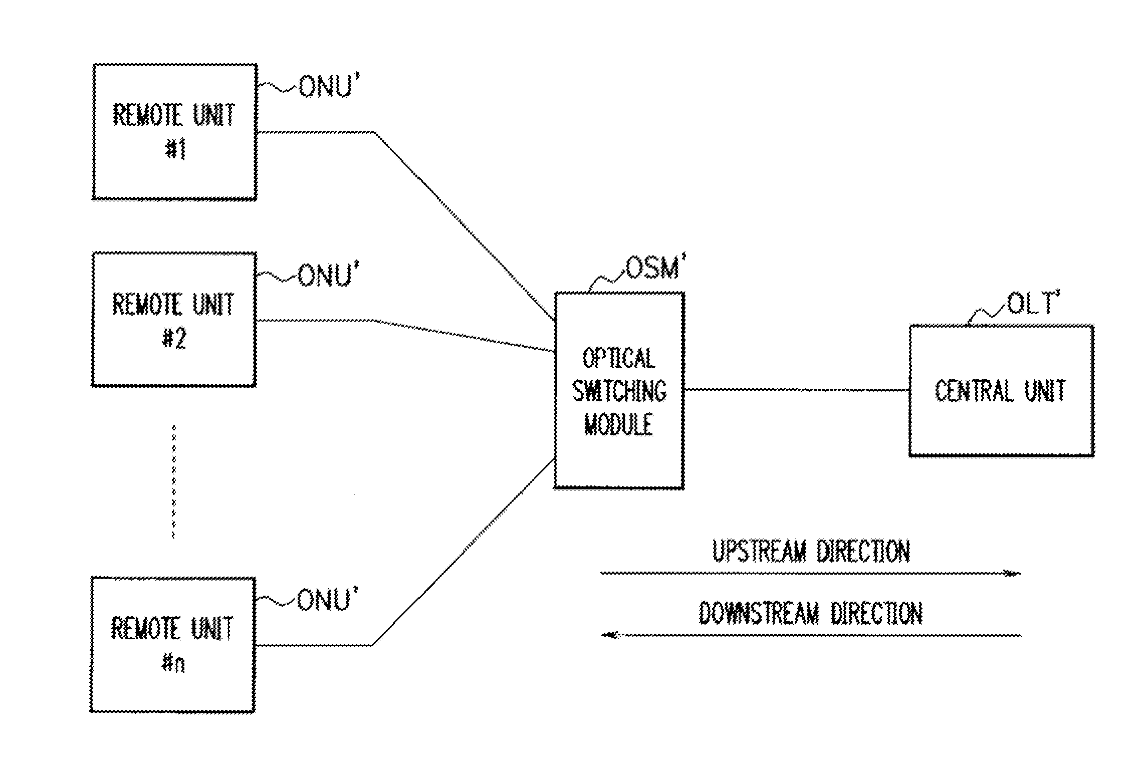
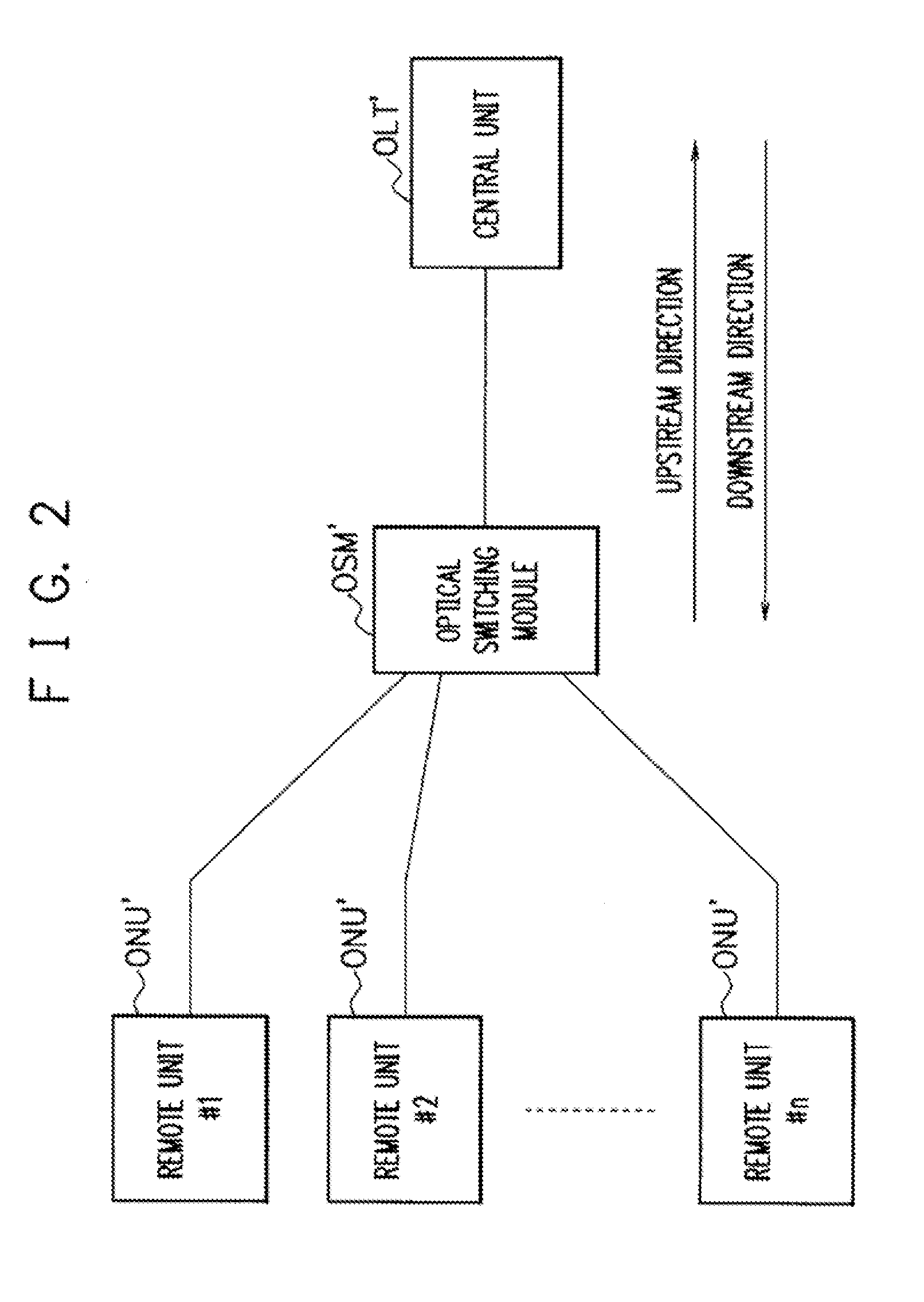
[0048]First, the system structure of an optical access network according to a first exemplary embodiment will be described with reference to FIG. 4. The optical access network shown in FIG. 4 is a GE-OSAN (Gigabit Ethernet-Optical Switched Access Network).

[0049]The optical access network according to this exemplary embodiment includes a central unit (OLT), an optical switching module (OSM), and remote units (ONU). In addition, the remote units (ONU) according to this exemplary embodiment are connected to the optical switching module (OSM) in a tree shape.

[0050]As shown in FIG. 5, the central unit (OLT) transmits a DC-balanced optical continuous signal including a packet signal in a downstream direction.

[0051]In addition, the central unit (OLT) according to this exemplary embodiment transmits a DC-balanced optical continuous signal including packets having identification information for identifying each of the remote units (ONU) to the optica...

second exemplary embodiment

[0077]Next, a second exemplary embodiment will be described.

[0078]In the first exemplary embodiment, as shown in FIG. 7, the remote unit (ONU) of the optical access network uses a receiving circuit including the AGC (2) and the low pass filter (3) to acquire packets transmitted to the remote unit (ONU).

[0079]The second exemplary embodiment is characterized in that, as shown in FIG. 10, a remote unit (ONU) of an optical access network uses a receiving circuit including an AGC (2), a first low cut filter (31), and a second low cut filter (32) to acquire packets transmitted to the remote unit (ONU).

[0080]In this way, similar to the first exemplary embodiment, the remote unit (ONU) according to this exemplary embodiment can use an inexpensive receiving circuit capable of satisfying the burst reception conditions of the remote unit (ONU′) to acquire packets transmitted to the remote unit (ONU). Hereinafter, the optical access network according to the second exemplary embodiment will be d...


PUM


Abstract

The present invention is to provide an optical access network in which a remote unit receives an optical burst signal. A central unit (OLT) transmits a DC-balanced optical continuous signal including packets having identification information for identifying each remote unit (ONU) to an optical switching module (OSM). The optical switching module (OSM) receives the DC-balanced optical continuous signal from the central unit (OLT), optically switches the packets based on the identification information, and transmits a DC-balanced optical burst signal including the packets to the remote unit (ONU). The remote unit (ONU) receives the DC-balanced optical burst signal and acquires the packets transmitted to the remote unit (ONU).

Description

TECHNICAL FIELD[0001]The present invention relates to an optical access network, and more particularly, to an optical access network that controls an optical burst signal, a remote unit, an optical communication method, and an optical communication program.BACKGROUND ART[0002]For example, a GE-PON (Gigabit Ethernet-Passive Optical Network) defined by IEEE Std 802.3 (IEEE Standard for Information technology—Telecommunications and information exchange between systems-Local and metropolitan area networks—Specific requirements, Dec. 9, 2005) has been known as a technique related to an optical access network according to the present invention (for example, see Non-Patent Document 1).[0003]The GE-PON disclosed in Non-Patent Document 1 transmits an IEEE802.3 frame (Ethernet frame) at a gigabit rate.[0004]As shown in FIG. 1, the GE-PON includes a central unit (OLT′: Optical Line Terminal), a plurality of remote units (ONU′: Optical Network Unit), and an optical splitter (SP) provided thereb...

Claims


Application Information

Patent Timeline
IPC IPC(8): H04J14/00H04B10/27H04B10/272H04B10/40H04B10/43H04B10/50H04B10/516H04B10/524H04B10/54H04B10/60H04B10/61
CPCH04Q11/0067H04Q11/0066
Inventor NOMURA, TAKUMIUEDA, HIROMIKURIYAMA, TAKASHITSUBOI, TOSHINORIKASAI, HIROYUKIKOBAYASHI, HIROKAZU
Owner NEC COMM SYST
Why Eureka
Try Eureka