Guide Bar for the Saw Chain of a Power Saw

Inactive Publication Date: 2011-01-20
ANDREAS STIHL AG & CO KG
View PDF14 Cites 8 Cited by
  • Summary
  • Abstract
  • Description
  • Claims
  • Application Information

AI Technical Summary

Benefits of technology

It has been shown that the known rivet connections can become loose due to the stresses that occur during operation, so that the guide bar can no longer be used. To prevent this loosening of the rivet connections, it is proposed p

Problems solved by technology

It has been shown that the known rivet connections can become loose due to the s

Method used


Image

  • Guide Bar for the Saw Chain of a Power Saw
  • Guide Bar for the Saw Chain of a Power Saw
  • Guide Bar for the Saw Chain of a Power Saw

Examples


Embodiment Construction

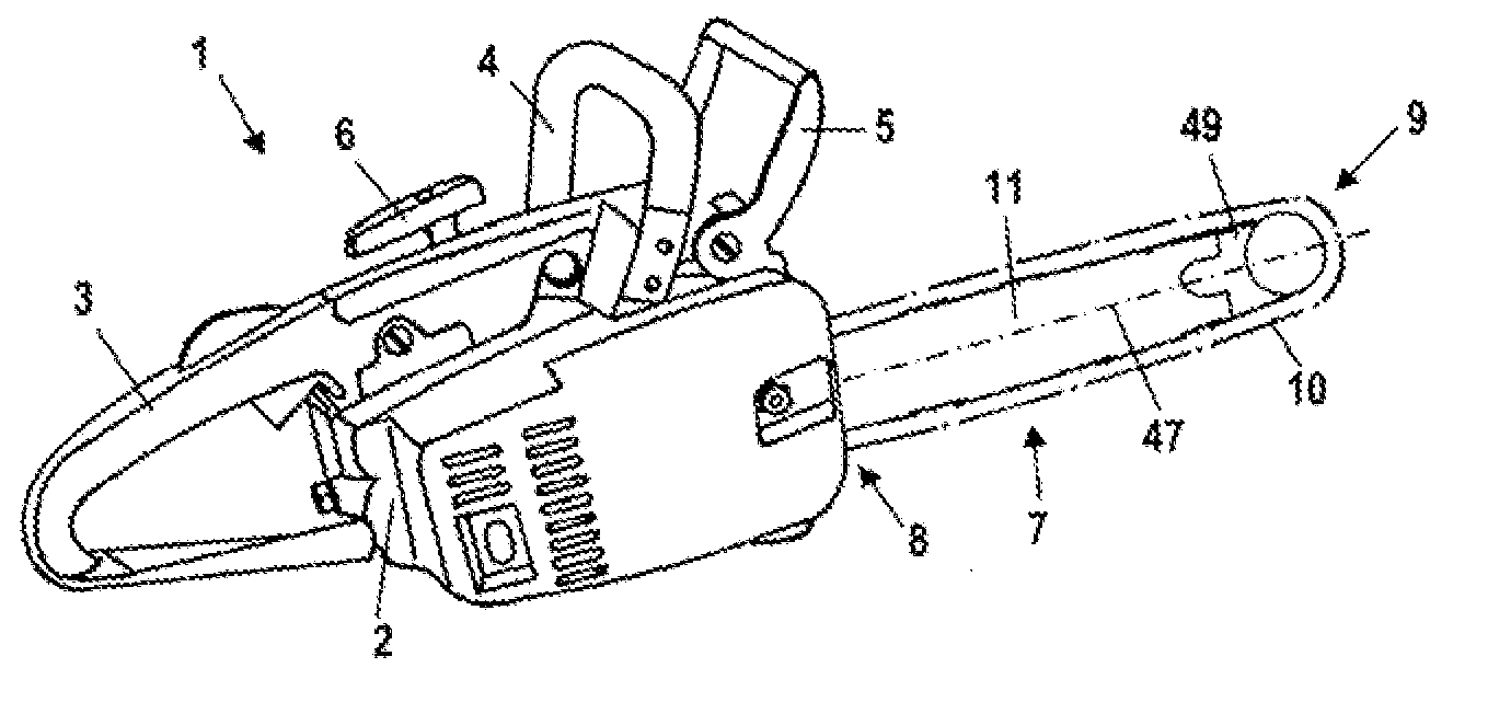
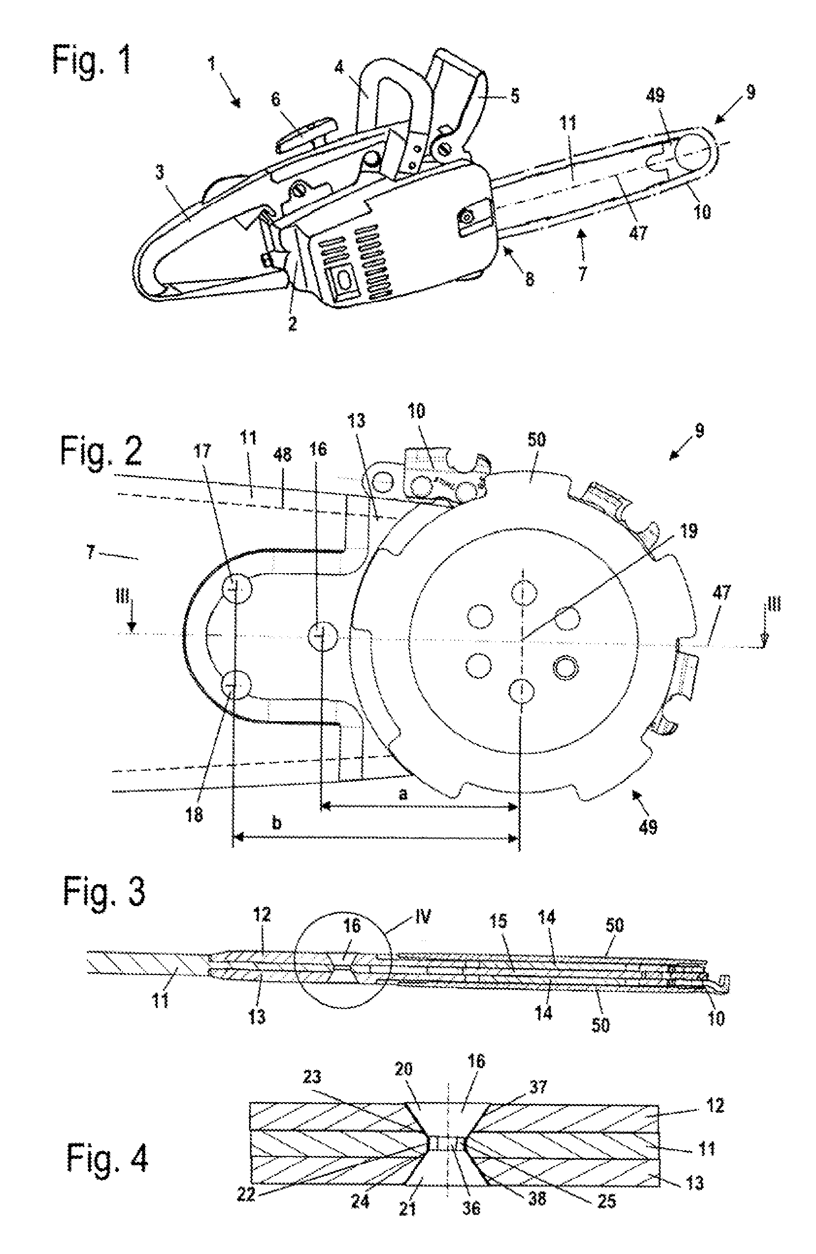
Referring now to the drawings in detail, FIG. 1 shows a power saw 1, which has a housing 2. Disposed in the housing 2 is a drive motor, which in the illustrated embodiment is an internal combustion engine that is started by a starter or pull handle 6. The internal combustion engine is advantageously a single cylinder, two-cycle engine, or a mixture-lubricated, four-cycle engine. However, an electric motor can also be provided as the drive motor. A rear handle 3 and a tubular handle 4 are mounted on the housing 2 for guiding the power saw 1. On that side of the housing 2 that faces away from the rear handle 3, a guide bar 7 extends toward the front. A saw chain 10, which is schematically illustrated in FIG. 1, is disposed on the guide bar 7 in such a way that it circulates thereon. The saw chain 10 is circulated by the drive motor. On that side of the tubular handle 4 that faces the guide bar 7 a finger guard 5 is disposed on the housing 2 for actuating a chain braking mechanism.

The ...


PUM

PropertyMeasurementUnit
Angleaaaaaaaaaa
Angleaaaaaaaaaa
Depthaaaaaaaaaa

Abstract

A guide bar for the saw chain of a power saw, including an elongated, planar main body having an outer periphery that is provided with a guide groove for guiding a saw chain. A direction-changing section is disposed at a free end of the guide bar and includes two side plates. At least one rivet is provided for securing the side plates to the main body, with the rivet extending through an opening in the main body. On at least one side of the main body, the opening is provided with a flared depression for receiving an adjacent element.

Description

The instant application should be granted the priority date of Jul. 15, 2009, the filing date of the corresponding German patent application 10 2009 033 213.8.BACKGROUND OF THE INVENTIONThe present invention relates to a guide bar for the saw chain of a power saw, wherein the guide bar is provided with a direction-changing section at its free end.A guide bar having a direction-changing section is known from U.S. Pat. No. 6,588,110 B2. The direction-changing section can be secured to the main body vie different types of securement means, for example via the rivet shown in this document.The securement of the direction-changing section to a main body must, with the dynamic stresses encountered during operation, have an adequately high strength, so that the direction-changing section is always reliably held on the main body.It is therefore an object of the present application to provide a guide bar of the aforementioned general type that achieves a good fixation of the direction-changin...

Claims


Application Information

Patent Timeline
IPC IPC(8): B27B17/02
CPCB27B17/02
Inventor GALSTER, WERNER
Owner ANDREAS STIHL AG & CO KG
Why Eureka
Try Eureka