Internal conduit vehicle and method for performing operations in a pipeline

a conduit vehicle and conduit technology, applied in the direction of railway tunnels, pipe elements, railway tracks, etc., can solve the problems of limited climbing ability of steep pipelines, limited work load, and blockage of bearings

Inactive Publication Date: 2011-01-20
HELIX TECH
View PDF6 Cites 24 Cited by
  • Summary
  • Abstract
  • Description
  • Claims
  • Application Information

AI Technical Summary

Benefits of technology

[0005]It is an object of the present invention to provide an internal conduit vehicle that may travel along steep ranges in a pipeline.

Problems solved by technology

This means that they may perform well in horizontal pipelines, but have a very limited ability of climbing steep pipelines.
This also means that they may only carry very limited work loads, i.e. they cannot drag heavy tools or cables along a pipeline.
Another shortcoming is that they are very restricted when it comes to passing bends or T-sections in a pipeline, in that the elements bearing the wheels may get blocked against the different angles or departing walls.

Method used


Image

  • Internal conduit vehicle and method for performing operations in a pipeline
  • Internal conduit vehicle and method for performing operations in a pipeline
  • Internal conduit vehicle and method for performing operations in a pipeline

Examples


Embodiment Construction

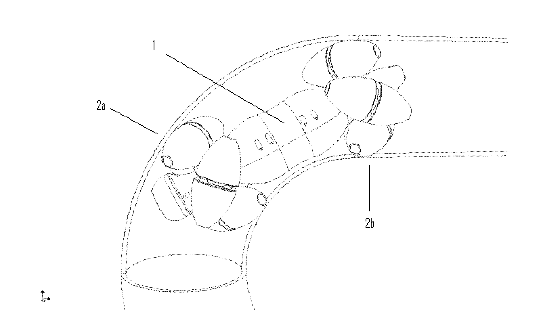
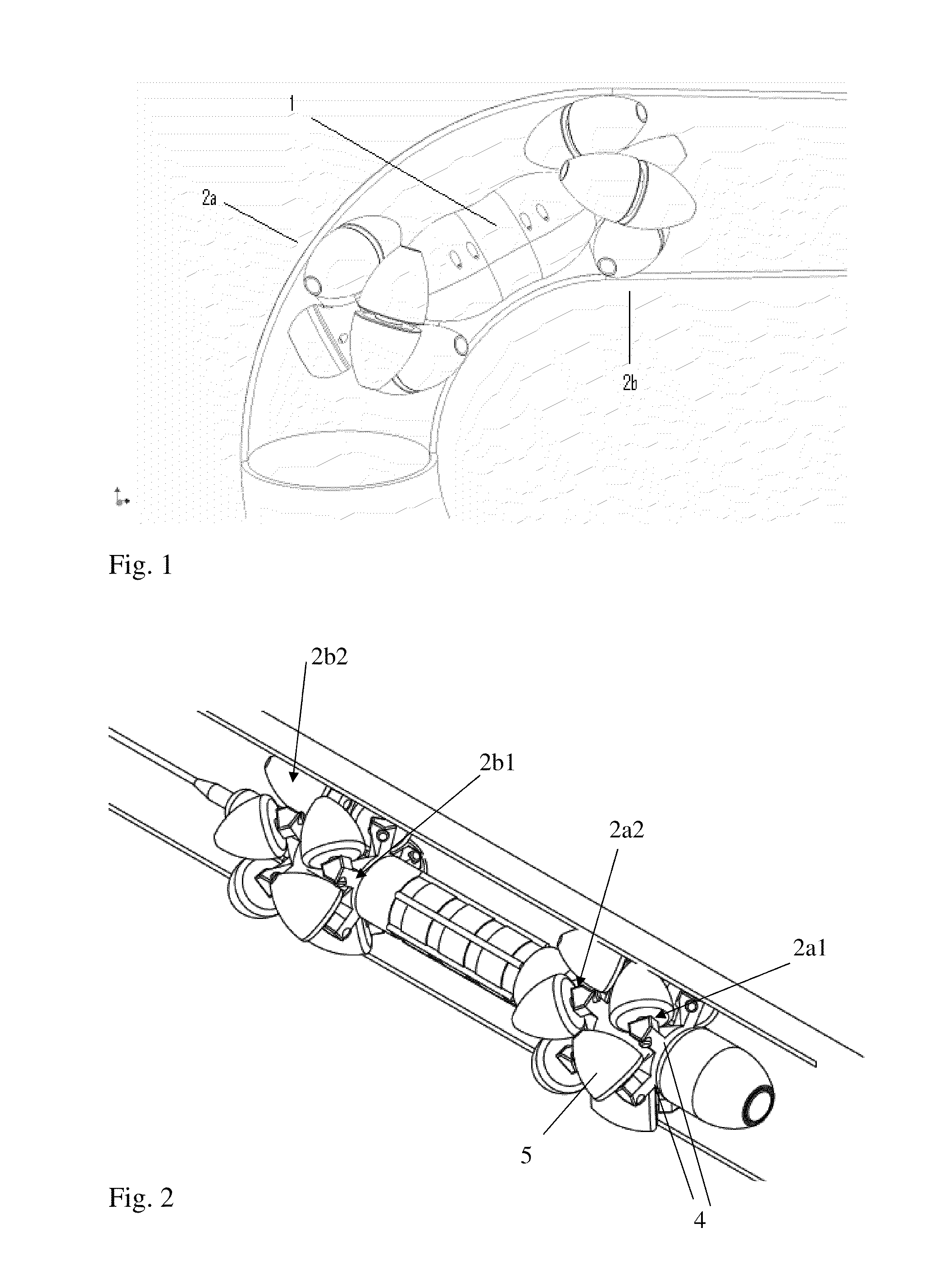
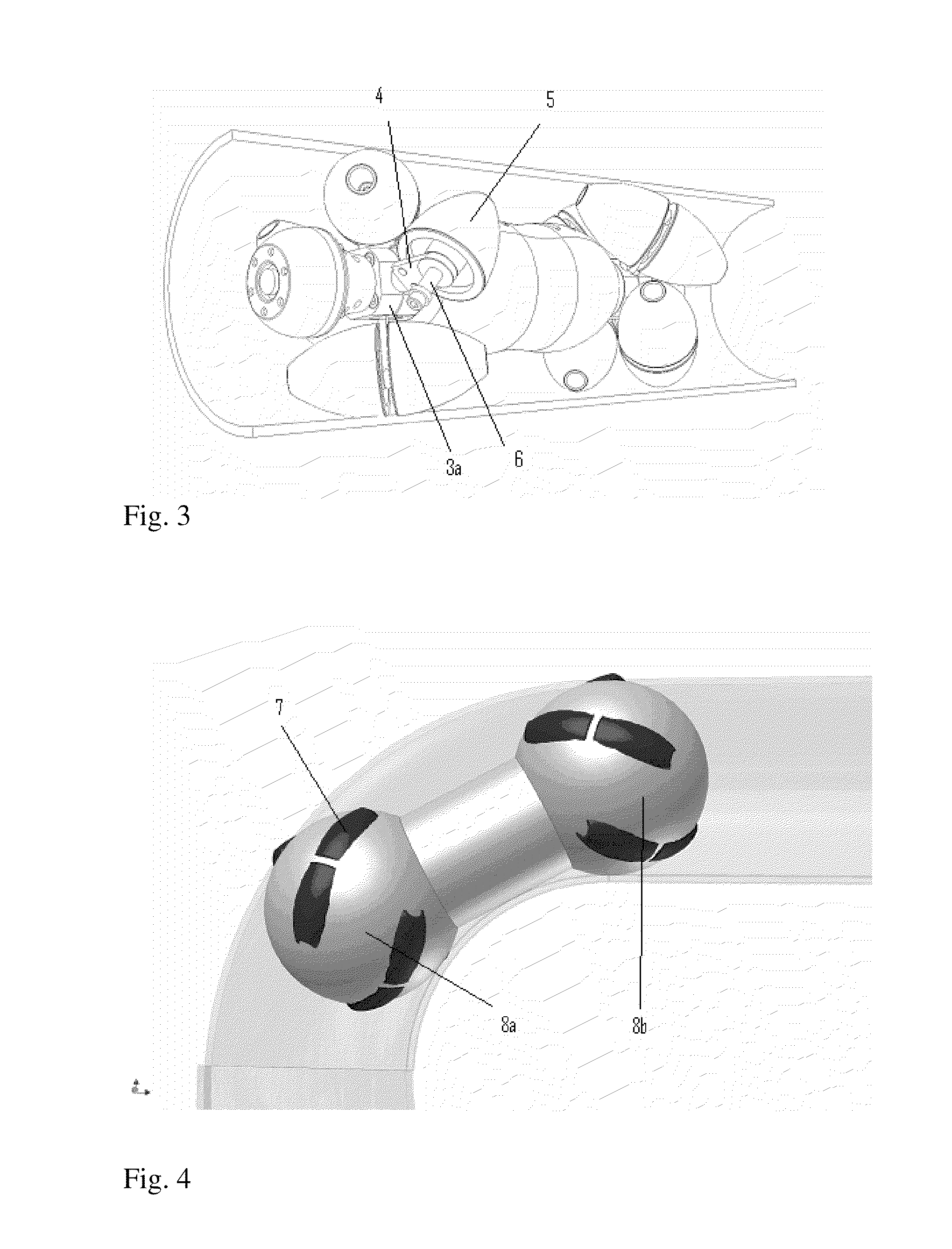
[0023]FIG. 1 shows an embodiment of the invention when passing a bend in a pipeline. The vehicle includes a chassis 1 with a first wheel assembly 2a mounted in one end and a second wheel assembly 2b mounted in the other end. Each wheel assembly 2a, b includes a hub 3a, b (FIG. 3) carrying a number of wheel arms 4 protruding as spokes from each hub. On each wheel arm 4 there is mounted at least one freely rotating wheel 5. Motor drives inside the chassis are adapted to rotate the wheel assemblies in counteracting directions to propel the vehicle along the pipe.

[0024]Each wheel 5 is a rotation symmetric body with a small end and a big end. This means that the wheel may be shaped e.g. as a truncated cone, a half ellipsoid or cup. The wheels shown in FIG. 2 are shaped as half-ellipsoid cups. This particular design of the wheels, which are preferably made from an elastic material, acts to distribute the pressure increasing the footprint on the pipe wall, but in a gentle way preventing da...


PUM


Abstract

An internal conduit vehicle, also called a pipeline vehicle. The vehicle includes first and second wheel assemblies that are rotated in opposite directions to move the vehicle along the pipeline, or that are mutually independent to perform a more complex movement. Each wheel assembly includes a number of wheels at the free end of wheel arms, each wheel having a spin axis that is angled in respect of an axis of the chassis. Each wheel is shaped as a rotation symmetric body with a large end and a small end, and is unilaterally mounted to a wheel arm by the large end.

Description

FIELD OF THE INVENTION[0001]The present invention relates to an internal conduit vehicle, also called a pipeline tractor or pipeline vehicle, which is a device travelling inside a pipeline transporting measuring instruments and tools. Such devices are in particular in use in the oil and gas industry, but may also find use in other fields, such as for inspecting and cleaning water pipes, sewers or ventilation tubes. According to a second aspect the present invention relates to a method for performing operations in a pipeline by use of a pipeline vehicle.BACKGROUND[0002]Several varieties of pipeline vehicles have been made in the past based on different technologies. Some use the fluid flowing in the pipeline for propulsion (pigs) or move along with worm-like movements. Others use wheels or belts for moving along the pipeline.[0003]From U.S. Pat. No. 5,551,349 to Bodzin there is known a pipeline vehicle comprising two coaxially aligned wheel assemblies mounted to each end of a chassis...

Claims


Application Information

Patent Timeline
Patent Type & Authority Applications(United States)
IPC IPC(8): F16L55/18F16L55/28
CPCF16L55/28B60B19/003F16L55/30F16L55/32
Inventor BECK, ESBEN
Owner HELIX TECH
Why Eureka
Try Eureka