Vacuum chuck spinstand for testing magnetic heads and disks

a spinstand and vacuum chuck technology, applied in the field of vacuum chucks, can solve the problems of unreliable spinstand operation, track misregistration reaches unacceptable levels, and the track misregistration increases, so as to achieve quick and accurate centering and quick removal

Inactive Publication Date: 2007-11-13
GUZIK TECHN ENTERPRISES
View PDF7 Cites 25 Cited by
  • Summary
  • Abstract
  • Description
  • Claims
  • Application Information

AI Technical Summary

Benefits of technology

[0012]The present disclosure is directed to an apparatus and method which mitigates the aforementioned prior art limitations. According to one exemplary embodiment of the present disclosure, the apparatus comprises a vacuum chuck that uses a vacuum to consistently and quickly secure a disk to a spindle of a spinstand with a known and repeatable clamping force. The present disclosure provides a method for quickly removing the disk from the spindle by reversing the air pressure from a vacuum to a pressure greater than atmospheric pressure, ejecting the cap assembly. The present disclosure also provides a method for quickly and accurately centering the removable portion of the chuck about the axis of spindle rotation using an internal centering pin and locating hole.
[0015]The vacuum chuck assembly is coupled to the output drive element for removably positioning the pack in the disk pack region so that said DPA is coaxial with the spin axis in response to a selectively applied vacuum.

Problems solved by technology

These vibrations increase track misregistration.
In some cases, track misregistration reaches unacceptable levels at which spinstand operation becomes unreliable.
This method allows quick replacement of a disk, but it can still distort the disk due to the discreet number of clamping points.
Furthermore, the overall clamping force is limited, potentially resulting in instability.
However, this method creates problems for testing where the disk must be replaced repeatedly.
The force is dependant upon the fastening torque, which can vary from one assembly to another, and the screw must be manually inserted and removed with each disk change, adding significant time to the process.
Using a screw to hold the cap against the disk also makes automation of chuck insertion and removal difficult.

Method used


Image

  • Vacuum chuck spinstand for testing magnetic heads and disks
  • Vacuum chuck spinstand for testing magnetic heads and disks
  • Vacuum chuck spinstand for testing magnetic heads and disks

Examples


Embodiment Construction

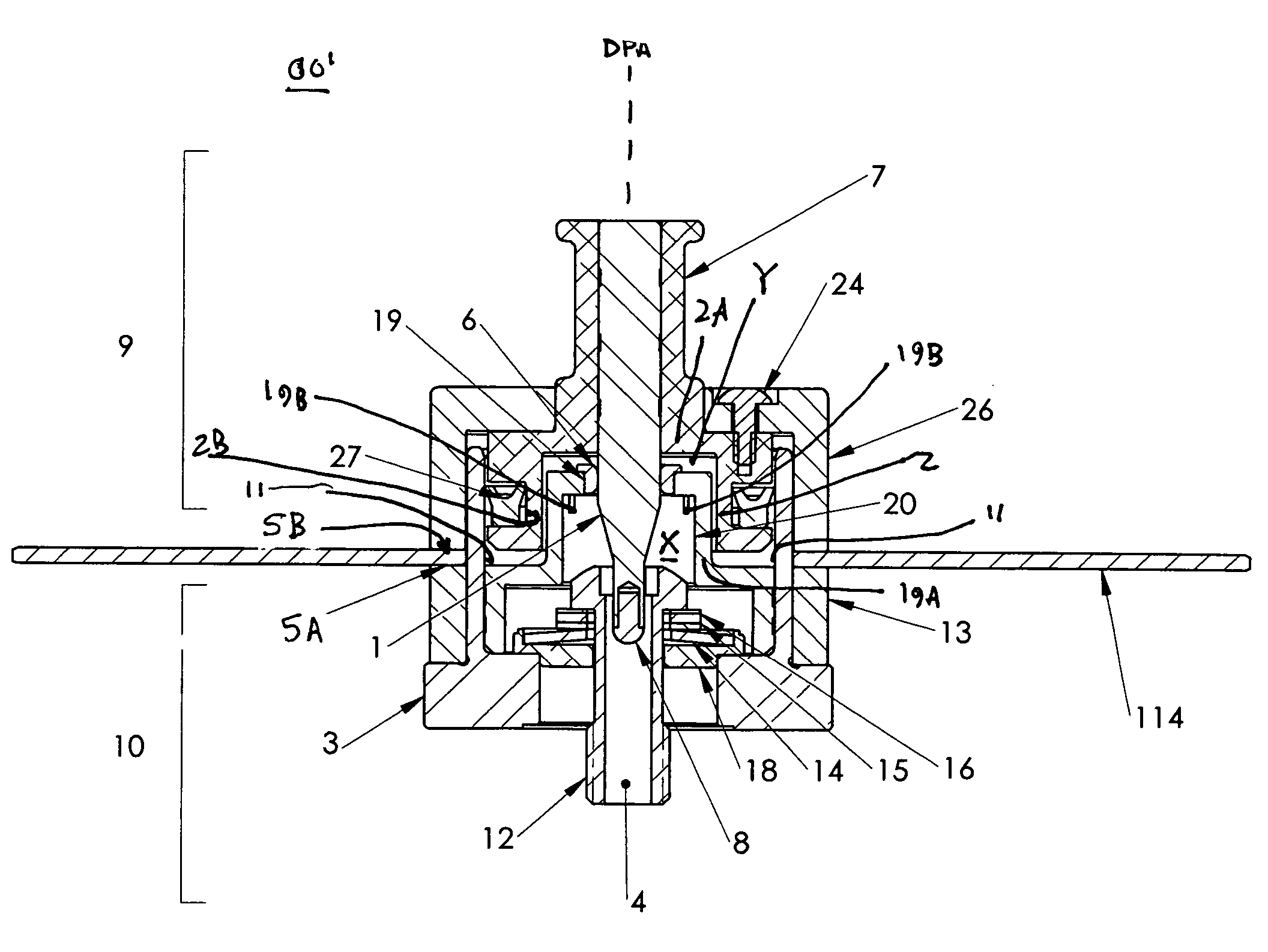
[0039]Referring first to FIGS. 3-8, there is shown an exemplary embodiment of a vacuum chuck 00 constructed in accordance with the present invention for use with a spinstand. The chuck 00 is adapted to use an applied vacuum to consistently and quickly secure a magnetic disk 114 to a spindle with a known and repeatable clamping force. The disk 114 is secured between a lower disk support surface SA and cap assembly 9 and an upper disk support surface SB base assembly 10 of the vacuum chuck. A handle 21 extends from cap assembly 9. Preferably, there is no mechanical fastener connecting the cap assembly 9 to the base assembly 10.

[0040]The exemplary disk 114 is an annular structure with a central hole about a disk pack axis (DPA) and includes a fragile magnetic medium on one or both of the principal top and bottom surfaces. Typically, such disks are formed from a relatively hard material, such as glass. Although only a single disk 114 is shown in FIGS. 3-8, the “disk” may be in the form ...


PUM


Abstract

A spinstand having a vacuum chuck clamping mechanism for securing magnetic discs includes a cap (9) and a base (10). A disk-to-be-clamped is held between the cap (9) and the base (10). Vacuum, applied through a port (4) in a mounting screw (12) of the base, provides the clamping force. The vacuum is held constant using a circumferential seal (27) on a piston (2) of the cap, which extends into a cylindrical countering bushing (3) extending from the base. In one form, the cap (9) is centered about a spin axis (SA) extending through the base (10), using a hardened pin (1) extending from the cap and a locating bushing (19) affixed to the base. When the cap (9) is inserted into the base (10), the pin (1) prevents a piston (2) in the cap from contacting the inside walls / sealing surface (11) of the centering bushing (3) of the base. To remove the cap, positive air pressure is applied to the air passage (4), collapsing the seal (27), and forcing the cap (9) out of the base (10) without causing wear on the seal (27) or the sealing surface (11) of the centering bushing (3).

Description

RELATED APPLICATIONS [0001]The application claims priority to U.S. Provisional Patent Application Nos. 60 / 643,826, filed Jan. 14, 2005 and 60 / 651,562, filed Feb. 10, 2005.FIELD OF THE DISCLOSURE[0002]The present disclosure relates to spinstands and, in particular, to a vacuum chuck for securing disks mounted on and spun by a spindle of a spinstand.BACKGROUND OF THE DISCLOSURE [0003]A magnetic head and disk tester is an instrument that is used for testing the characteristics of magnetic heads and disks, such as a signal-to-noise ratio, track profile, etc. The tester should simulate those motions of the head with respect to the disk and the same rotational speeds of the disks that occur in an actual hard disk drive during operation. Each tester consists of two components, i.e., a mechanical component, commonly referred to as a spinstand, that performs movements of the head with respect to the disk, and an electronic component that is responsible for measurement, calculation, and analy...

Claims


Application Information

Patent Timeline
Patent Type & Authority Patents(United States)
IPC IPC(8): G01R33/12
CPCG11B5/012G11B5/455G11B17/038G11B5/4555G11B2005/001
Inventor GUZIK, NAHUMRAY, FOREST E.ARNOLD, CHARLES BRICE
Owner GUZIK TECHN ENTERPRISES
Why Eureka
Try Eureka