
Tool suspension assembly

a technology of tool suspension and assembly, which is applied in the field of tool suspension assembly, can solve the problems of inconvenient and versatile use of the conventional tool suspension assembly

Inactive Publication Date: 2011-01-20
KAO JUI CHIEN
View PDF17 Cites 23 Cited by
  • Summary
  • Abstract
  • Description
  • Claims
  • Application Information

AI Technical Summary

Benefits of technology

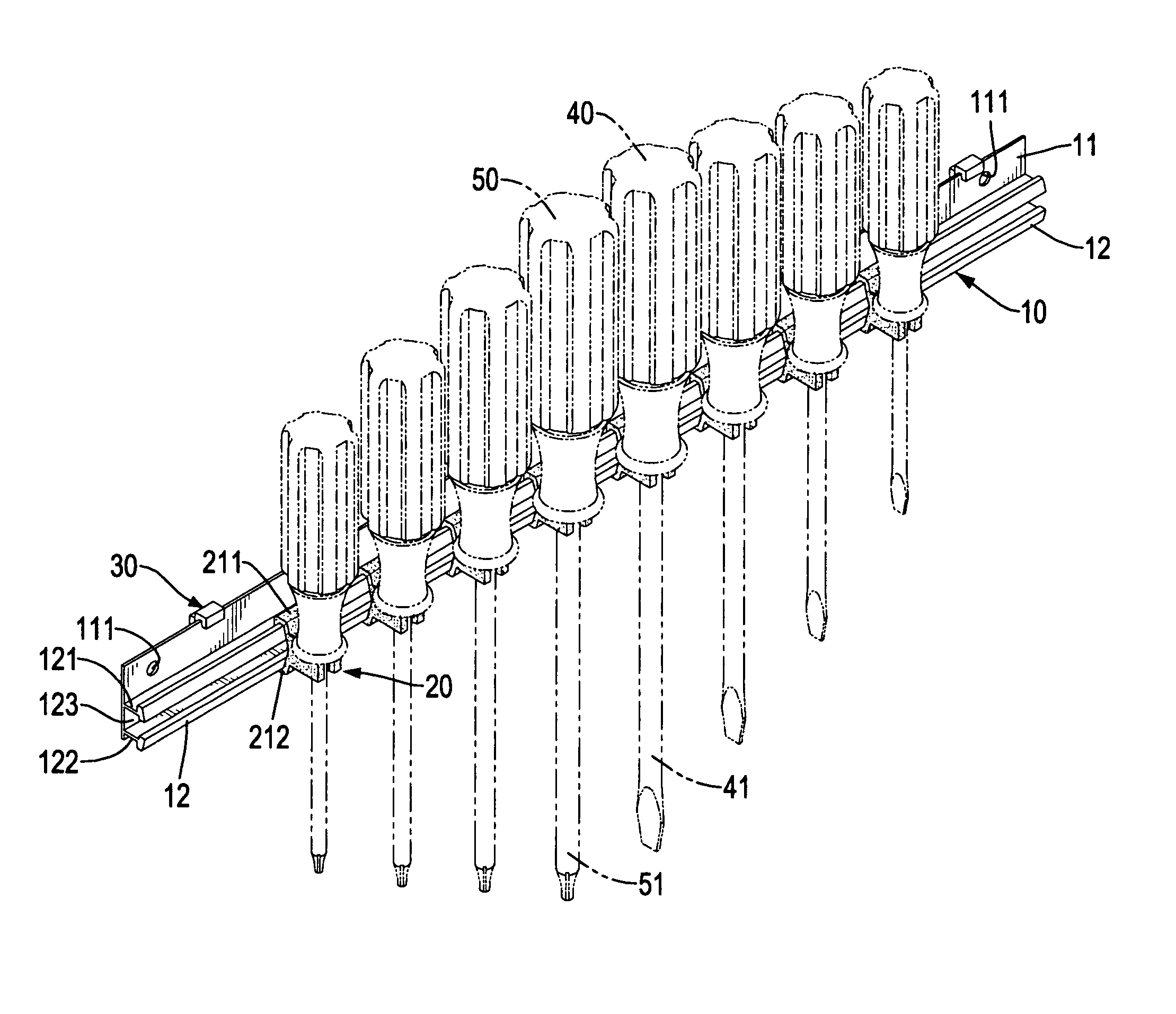
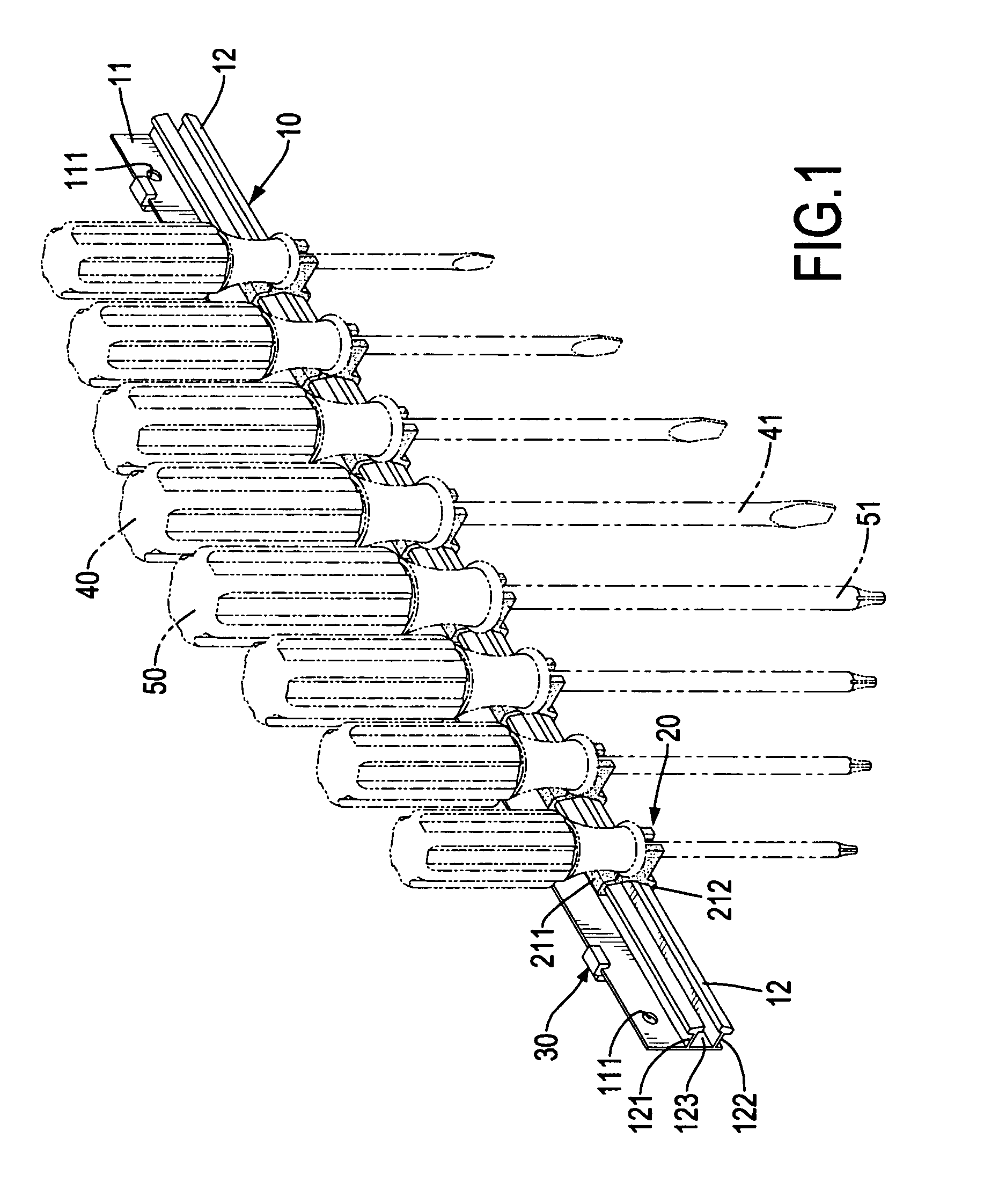
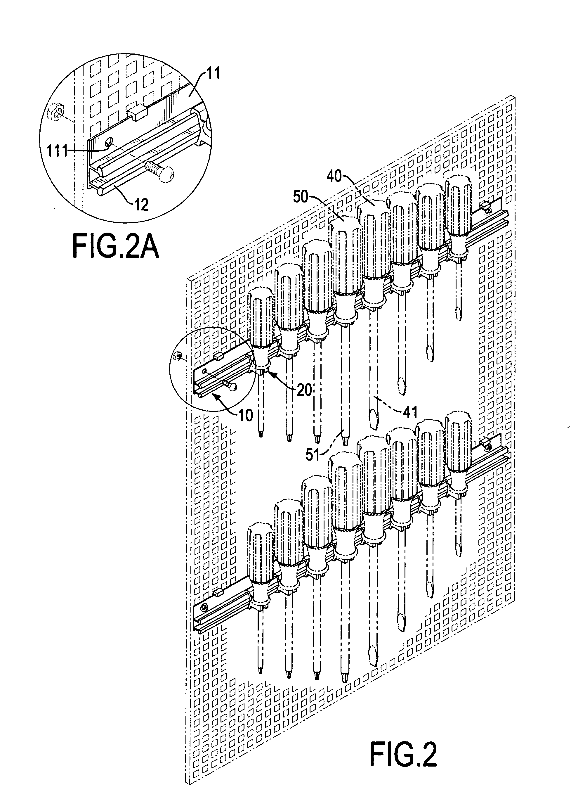
The main objective of the invention is to provide a tool suspension assembly that can hold tools in a convenient way. The tool suspension assembly has a base and multiple tool holders. The base is elongated and has a back board and a rail. The back board has a front side and a rear side. The rail is elongated and is longitudinally formed on and protrudes from the front side of the back board. The tool holders are slidably mounted on the rail on the base and each has a clamp, a tool mount and two oblique guiding tabs. The clamp is mounted slidably on the rail on the base. The tool mount is tubular, is connected to the clamp and has a C-shaped cross section, a first part and at least one second part. The C-shaped cross section makes the tool mount having an opening defined in a side of the tool mount opposite to the clamp. The at least one second part has a thickness smaller than that of the first part. The oblique guiding tabs are respectively and obliquely formed on and protruding from two sides of the opening of the tool mount.

Problems solved by technology

However, the intervals of the tool holders on the conventional tool suspension assembly are not adjustable, such that the use of the conventional tool suspension assembly is not convenient and versatile.

Method used


Image

  • Tool suspension assembly
  • Tool suspension assembly
  • Tool suspension assembly

Examples


first embodiment

In the first embodiment, each tool holder (20) may further have two connecting tabs (224) and a reinforced tab (225). The connecting tabs (224) are respectively connected to the lateral tabs (223) and to the clamp (21) of the tool holder (20). The reinforced tab (225) is laterally formed between and connected to middle portions of the clamp (21), the tool mount (22) and the connecting tabs (224). With the arrangement of the reinforced tab (225), the structural strength of the tool holder (20) is enhanced. With the arrangement of the connecting tabs (224) and the reinforced tab (225), the tool mount (22) is connected to the clamp (21).

second embodiment

With reference to FIGS. 7 to 9, in the second embodiment, each tool holder (22A) further has two connecting tabs (224A) mounted between the tool mount (22A) and the clamp (21A) of the tool holder (20A) to connect the tool mount (22A) to the clamp (21A).

With reference to FIGS. 6 and 6A, the hanging elements (30) are attached to the rear side of the back board (11), and each hanging element (30) having a hanging board (31), two base hooks (32) and a panel hook (33). The hanging board (31) has a top, a bottom, a front side attached to attached to the rear side of the back board (11) and a rear side. The base hooks (32) are formed respectively on the top and bottom of the hanging board (31), protrude from the front side of the hanging board (31) and are mounted over and hook on a top edge and a bottom edge of the back board (11) in respective. The panel hook (33) is formed on and protrudes from the rear side of the hanging board (31) to be inserted into or engage a hole defined in a han...


PUM


Abstract

A tool suspension assembly has a base and multiple tool holders. The base is elongated and has a back board and a rail. The rail is elongated and is longitudinally formed on the back board. The tool holders are slidably mounted on the rail and each has a clamp, a tool mount and two oblique guiding tabs. The clamp is mounted slidably on the rail. The tool mount is tubular, is connected to the clamp and has a C-shaped cross section, a first part and at least one second part. The C-shaped cross section makes the tool mount having an opening. The at least one second part has a thickness smaller than that of the first part. The oblique guiding tabs are respectively and obliquely formed on and protruding from two sides of the opening of the tool mount.

Description

BACKGROUND OF THE INVENTION1. Field of the InventionThe present invention relates to a tool suspension assembly, and more particularly to a tool suspension assembly that can hold tools in a convenient way.2. Description of Related ArtA tool suspension assembly can hold multiple tools, such as screwdrivers or wrenches and is always attached to an object for storing or displaying the tools on the wall. A conventional tool suspension assembly has multiple tool holders arranged at intervals for holding tools thereon. However, the intervals of the tool holders on the conventional tool suspension assembly are not adjustable, such that the use of the conventional tool suspension assembly is not convenient and versatile.To overcome the shortcomings, the present invention tends to provide a tool suspension assembly to mitigate or obviate the aforementioned problems.SUMMARY OF THE INVENTIONThe main objective of the invention is to provide a tool suspension assembly that can hold tools in a co...

Claims


Application Information

Patent Timeline
Patent Type & Authority Applications(United States)
IPC IPC(8): A47F7/00
CPCB25H3/04
Inventor KAO, JUI-CHIEN
Owner KAO JUI CHIEN
Learn More