Valve

a valve and valve body technology, applied in the field of valves, can solve the problems of shortening the tool life and service life, local load peak, and high surface pressure between the shaft liner, and achieve the effect of increasing stiffness and functional reliability

Active Publication Date: 2011-01-20
XOMOX INT
View PDF5 Cites 11 Cited by
  • Summary
  • Abstract
  • Description
  • Claims
  • Application Information

AI Technical Summary

Benefits of technology

[0006]The present invention provides a valve having a simple, yet functionally reliable design. The valve includes a rotational body and shaft that are securely joined to one another so as to be integrally embodied. The valve has an opening, and in the area of the opening the shaft includes a part having a spherical outer surface. The shaft is surrounded by a support ring that has a spherical inner surface that corresponds at least approximately to the spherical outer surface of the shaft part. The spherical outer surface of the shaft part is positioned against the spherical inner surface of the support ring, creating a pivot bearing about pivot axes. A center of the pivot bearing is defined by the center point and / or the center of the aforesaid spherical surfaces and / or is disposed at least approximately on a common rotational axis for the shaft and the rotational body. An annular sealing element is arranged in an annular gap of the opening between the shaft and the housing. The sealing element may have an X-shaped section. In the area of the spherical outer surfaces, the sealing element may have an annular part or support ring with increased stiffness. A bearing for the shaft is formed by the sealing element, the support ring, the spherical part of the shaft, and the rotational body about axes that run at least approximately orthogonal to the common rotational axis for the rotational body and shaft.

Problems solved by technology

The result is that local load peaks and quite high surface pressures occur between the shaft liner and the gland packing.
These shorten the tool life and service life and can lead to elevated leak rates, even after relatively short operating times.
Furthermore, hysteresis and / or positional differences between the angle of rotation position for the shaft and the angle of rotation position for the rotational body may occur, which are disadvantages.
These disadvantages are especially noteworthy for a control valve and / or in automated systems in which drives are provided that are suitable for rotating the shaft and ultimately the rotational body.
Still further, a special double seal provided in the area of the shaft opening requires a not insignificant structural volume and correspondingly complex production and assembly.

Method used


Image

  • Valve
  • Valve
  • Valve

Examples


Embodiment Construction

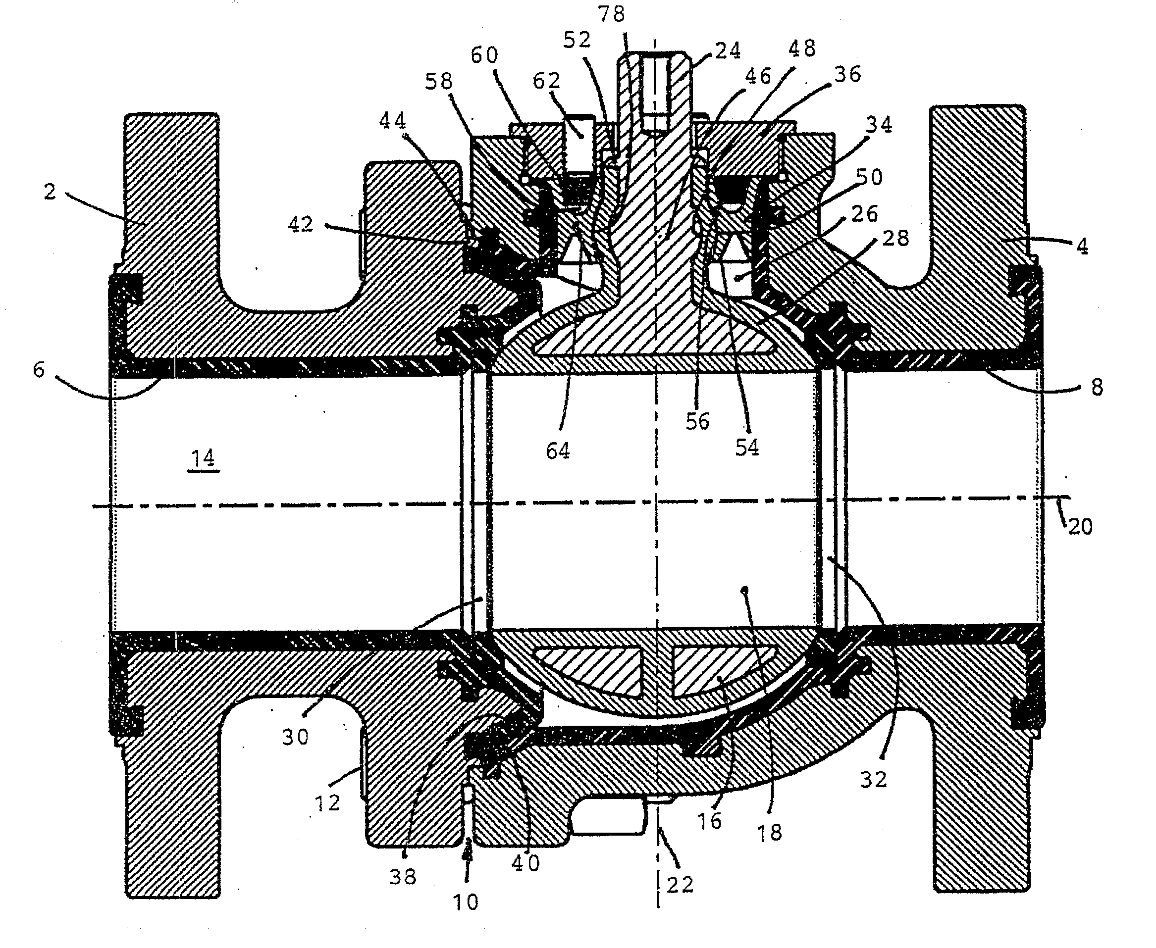
[0026]In accordance with FIG. 1, a ball valve includes a housing having two housing parts 2, 4 that are interiorly lined with plastic liners 6, 8. The housing may comprise a metal. The housing parts 2, 4 are joined to one another by screws 12 in a connecting area 10, such as at a flange connection. The liners 6, 8 delimit the flow channel 14 for a flow medium and are disposed in the interior of the housing. Arranged in the interior of the housing is a spherical rotational body 16 that includes a through-opening 18 and that can be rotated about a rotational axis 22 that is orthogonal to the longitudinal axis 20 of the housing. In the depicted open position the flow medium can flow freely through the through-opening 18 and thus through the valve. After the rotational body 16 has been rotated 90° with respect to the rotational axis 22, the rotational body 16 assumes its closed position for closing the flow path.

[0027]A shaft 24 is securely joined to the rotational body 16. The rotation...


PUM


Abstract

A valve includes a housing, a rotational body, two seat rings, a shaft integrally linked to the rotational body, and a sealing element. The rotational body is arranged rotatably in the housing and has a through-opening. The seat rings are spaced apart in the housing, each positioned against an outer surface of the rotational body to seal against leakage. The shaft extends outwardly through a housing opening. Part of the shaft has a spherical outer surface. The sealing element is positioned against the spherical outer surface, and includes a sealing lip and a support ring. The support ring has a spherical inner surface with a curvature corresponding to the spherical outer surface. The shaft is supported on the support ring at the shaft part's spherical outer surface. A flow path is defined by a housing through-opening and a rotational body through-opening, and is closed or at least partially open as determined by a rotational angle position of the rotational body about a rotational axis. The rotational body and shaft move together pivoting about a pivot axis that is orthogonal to the rotational axis. The pivot axis is determined by the shaft part's spherical outer surface.

Description

BACKGROUND OF THE INVENTION[0001]The present invention relates generally to a valve, and more particularly to a valve having a housing and a rotational body, such as a spherical rotational body, arranged rotatably therein.[0002]A ball valve is described in EP 1 047 894 B1 having a separately embodied shaft mechanically linked to a spherical rotational body of the valve. The rotational body includes a passage for a flow medium. The interior of a housing includes two seat rings that are spaced apart in the direction of flow. The rings are sealingly positioned against the outer spherical surface of the rotational body. A rectangular part of the shaft engages in a correspondingly embodied seat of the rotational body and is conducted through an opening in the housing to the outside. The rotational body may be rotated by means of a lever or the like into the desired position for closing or at least partially opening the flow path. Because the rotational body and shaft are embodied as two ...

Claims


Application Information

Patent Timeline
Patent Type & Authority Applications(United States)
IPC IPC(8): F16K5/06
CPCF16K5/0647F16K5/0657F16K41/08F16K27/067F16K41/046F16K5/0694
Inventor WETZEL, WINFRIEDWEIL, JOCHENDAVIDSON, JAMES WILLIAMFUOC, ALAINVORTKAMP, JAMES E.
Owner XOMOX INT
Why Eureka
Try Eureka