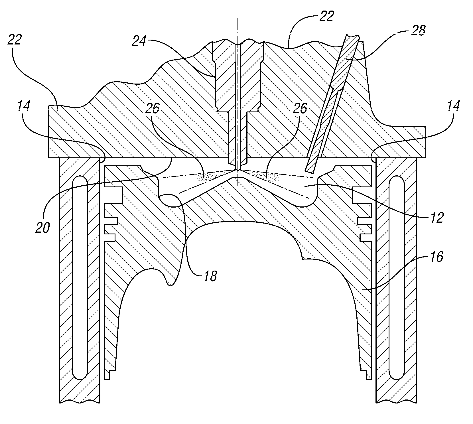
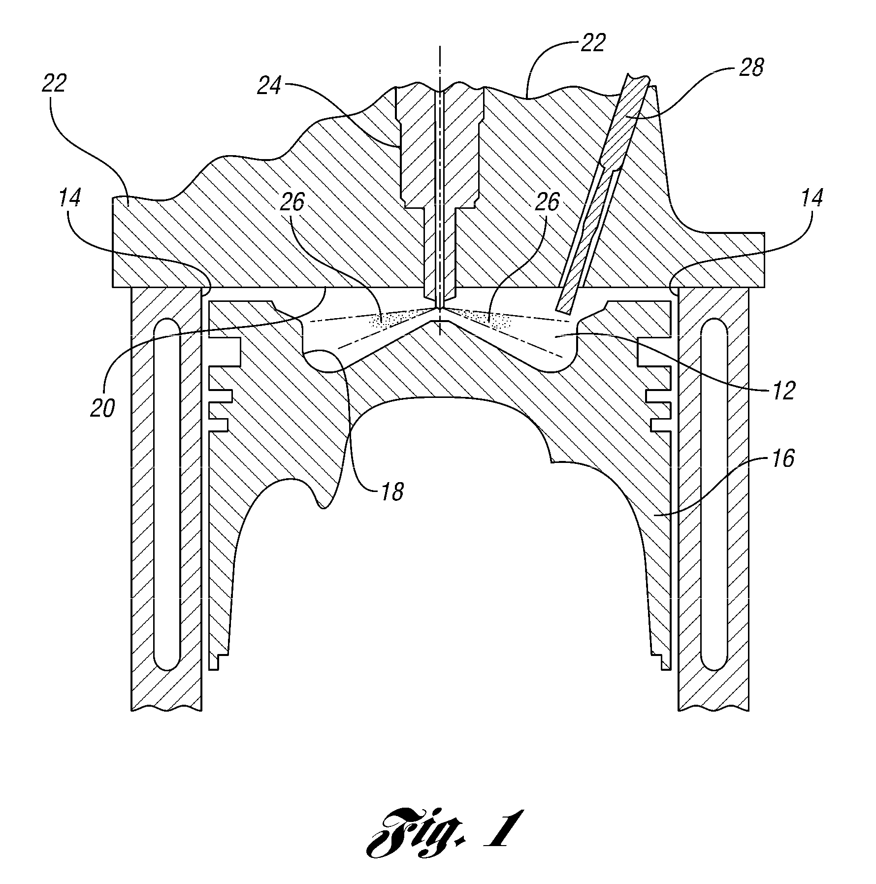
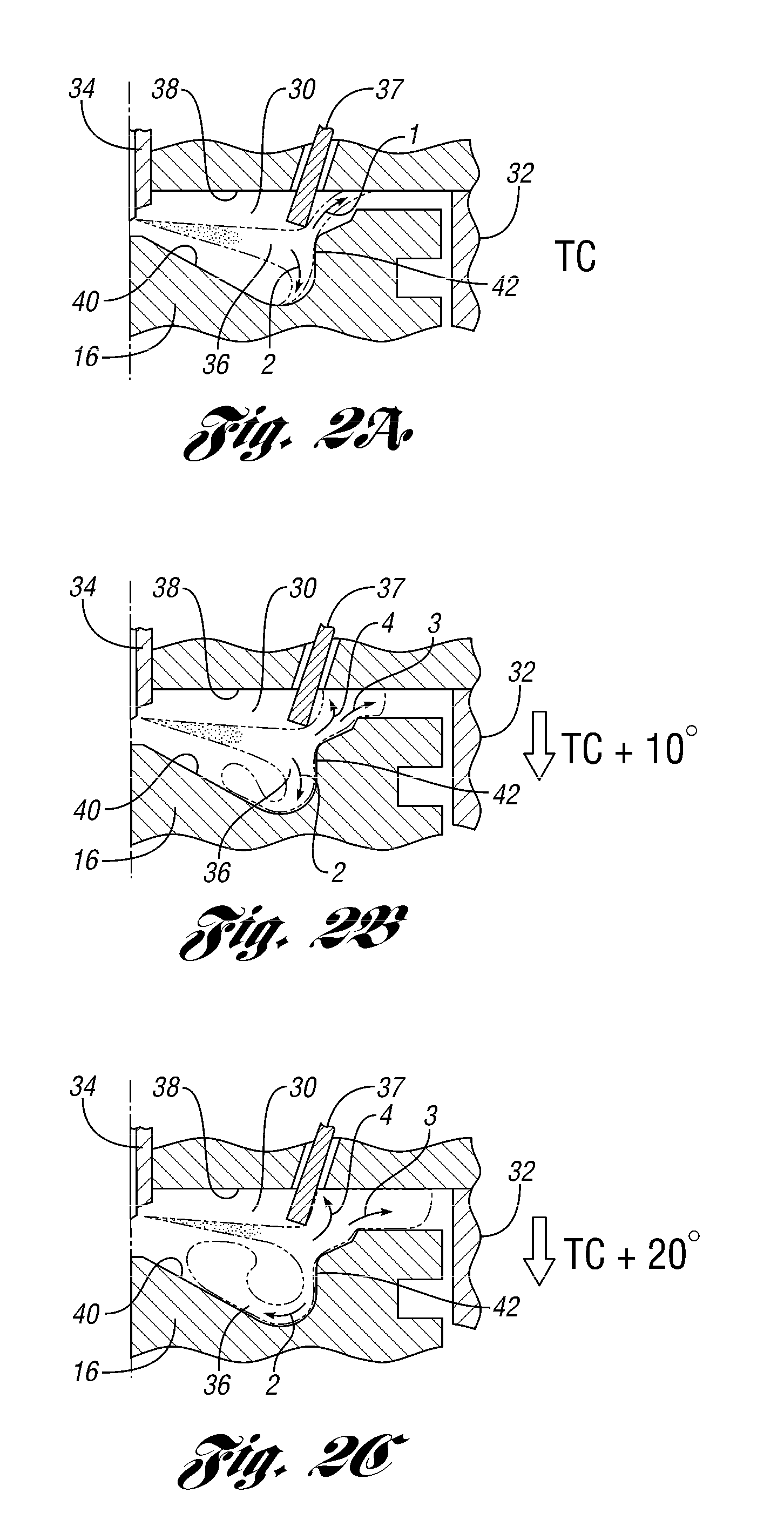
Glow plug placement in a diesel engine

a technology for diesel engines and glow plugs, which is applied in the direction of machines/engines, lighting and heating apparatus, electric control, etc., can solve the problems of little fuel travel, too lean rebound mixture, and compromise the strength of the cylinder head, so as to achieve less distortion and weakening of metal, no valve size nor strength at the valve bridge need to be compromised, and the effect of less distortion and weakening

Active Publication Date: 2011-02-03
FORD GLOBAL TECH LLC
View PDF22 Cites 29 Cited by
  • Summary
  • Abstract
  • Description
  • Claims
  • Application Information

AI Technical Summary

Benefits of technology

The present patent is about a new design for a combustion chamber in a diesel engine that improves performance and efficiency. The design includes a cylinder head with a centrally mounted injector and a piston bowl with a glow plug. The glow plug is positioned outboard of the valve bridge, which allows for two opportunities for the glow plug to interact with a combustible fuel mixture. The glow plug is also positioned close to the fuel jet path, which reduces the likelihood of liquid droplets impacting the glow plug. The design also includes a cylinder bowl with a vertical section that interacts with the fuel spray, improving fuel vaporization and ignition. The technical effects of the design include improved cold start performance, improved fuel vaporization and ignition, and increased fuel efficiency.

Problems solved by technology

The technical problem addressed in this patent text is how to improve the cold start and operation performance of diesel engines, particularly by using glow plugs to aid in cold start performance and minimizing misfire and white smoke during operation. The optimal compression ratio for best efficiency in real world engines is 15 to 1, but historically compression ratios of diesel engines were raised to levels much higher to increase compression temperatures in cold operation. The use of glow plugs in diesel engines is important to help engines meet lower emissions requirements, but their placement is critical to ensure full operational life and minimize impact on air flow. The glow plug is typically placed close to the injector nozzle to ensure suitable air and fuel concentration. However, in engines with 4 valves per cylinder, the placement of the glow plug can compromise the strength of the cylinder head and limit the maximum power that the engine can develop.

Method used


Image

  • Glow plug placement in a diesel engine
  • Glow plug placement in a diesel engine
  • Glow plug placement in a diesel engine

Examples


Embodiment Construction

[0022]As those of ordinary skill in the art will understand, various features of the embodiments illustrated and described with reference to any one of the Figures may be combined with features illustrated in one or more other Figures to produce alternative embodiments that are not explicitly illustrated or described. The combinations of features illustrated provide representative embodiments for typical applications. However, various combinations and modifications of the features consistent with the teachings of the present disclosure may be desired for particular applications or implementations. The representative embodiments used in the illustrations relate to placement of a glow plug in a 4-valve-per-cylinder engine that is outboard of the narrowest section of the valve bridge in between adjacent valves. Those of ordinary skill in the art may recognize similar applications or implementations consistent with the present disclosure, e.g., ones in which components are arranged in a...


PUM


Abstract

A four-valve per cylinder engine has two intake valves, two exhaust valves and a centrally located fuel injector. Between each adjacent pair of valves is a valve bridge with a point of minimum separation between adjacent valves. In the present disclosure, the glow plug port is defined in the cylinder top at a location outboard of the minimum separation between adjacent and at a depth which is tangent to an edge of a fuel jet emanating the injector. By placing the glow plug farther outboard than found in the prior art, the glow plug contacts the fuel as it comes out of the injector and as it rebounds off a feature of the piston bowl.

Description


Claims


Application Information

Patent Timeline
Owner FORD GLOBAL TECH LLC
Why Eureka
Try Eureka