Vehicle roof with at least two cover elements

Inactive Publication Date: 2011-02-03
WEBASTO AG
View PDF10 Cites 2 Cited by
  • Summary
  • Abstract
  • Description
  • Claims
  • Application Information

AI Technical Summary

Benefits of technology

[0009]The invention therefore relates to a vehicle roof with at least two cover elements which optionally close or at least partially open up a roof opening, of which a front cover element can be deployed with its rear edge above a fixed vehicle roof region and of which a rear cover element serves as a sliding cover and can be lowered under the fixed vehicle roof region and can be displaced along guide rails which are arranged on both sides of the roof opening and are fixed on the roof. An actuating mechanism for the two cover elements is designed in such a manner that it comprises for each guide rail a driving slide which is provided with a control track which interacts with a deployment lever for the front cover element, the deployment lever being coupled to a pivotable support of the front cover element. The deployment movement of the deployment lever is assisted by means of a spring. A robust mounting of the front cover element is made possible by the deployment movement being controlled by means of the driving slide and the deployment movement being assisted by the spring. In addition, the spring secures the front cover element in the deployed position. The mechanical prop formed by the deployment lever can also withstand high wind forces.
[0021]In order to reinforce the pivoting movement of the lifting and lowering lever for the rear cover element and therefore to increase the adjustment magnitude of the rear cover element, a reinforcing lever can be provided on which the lifting and lowering lever acts and which is guided with one end in a guide track of the guide rail and acts on the rear cover element with its other end. In particular, it can act on a pivotable support of the rear cover element.

Problems solved by technology

However, this has a disadvantageous effect for the closing of the front cover element, since high driving forces which counter the spring force are required.

Method used


Image

  • Vehicle roof with at least two cover elements
  • Vehicle roof with at least two cover elements
  • Vehicle roof with at least two cover elements

Examples


Embodiment Construction

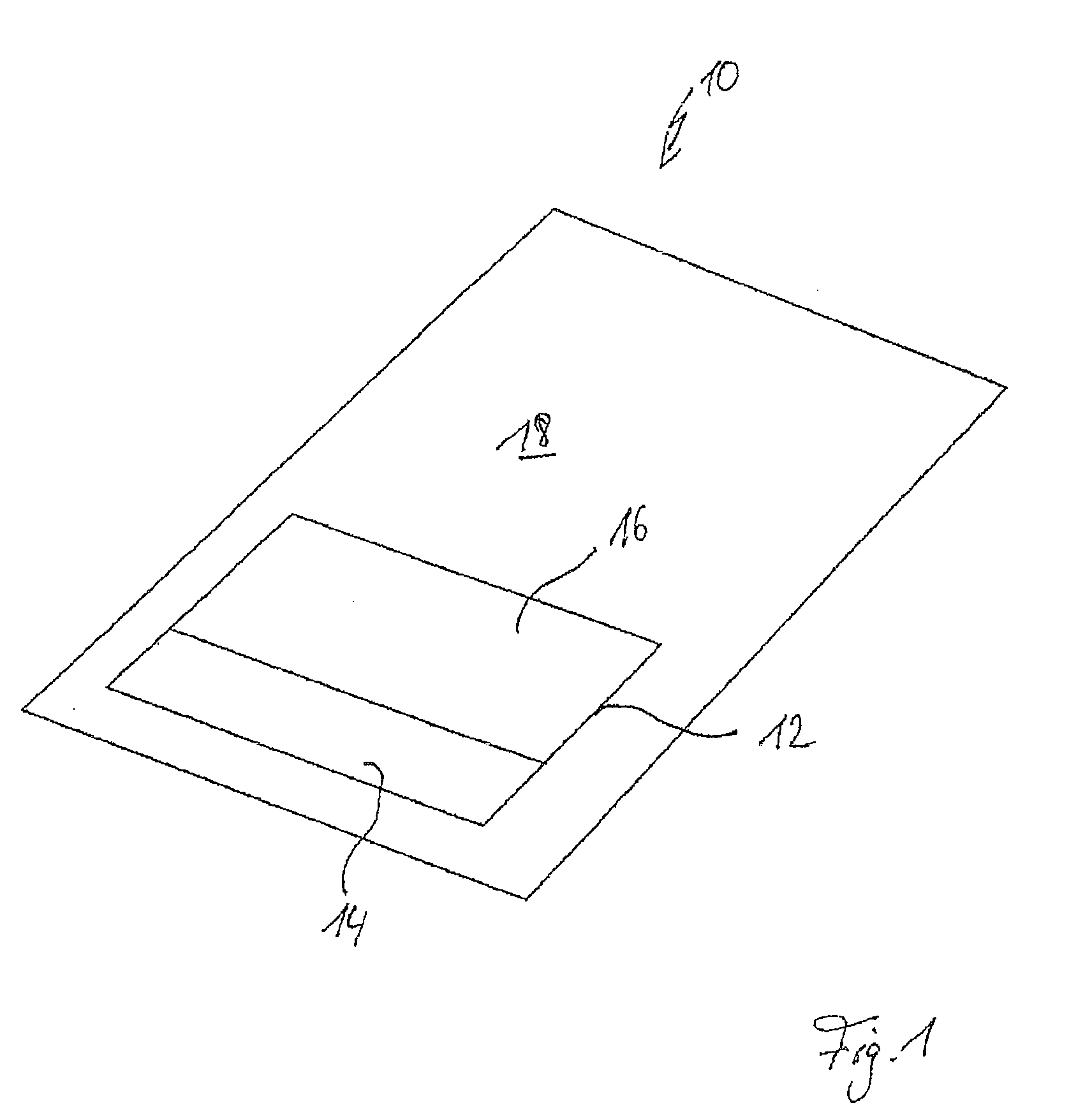
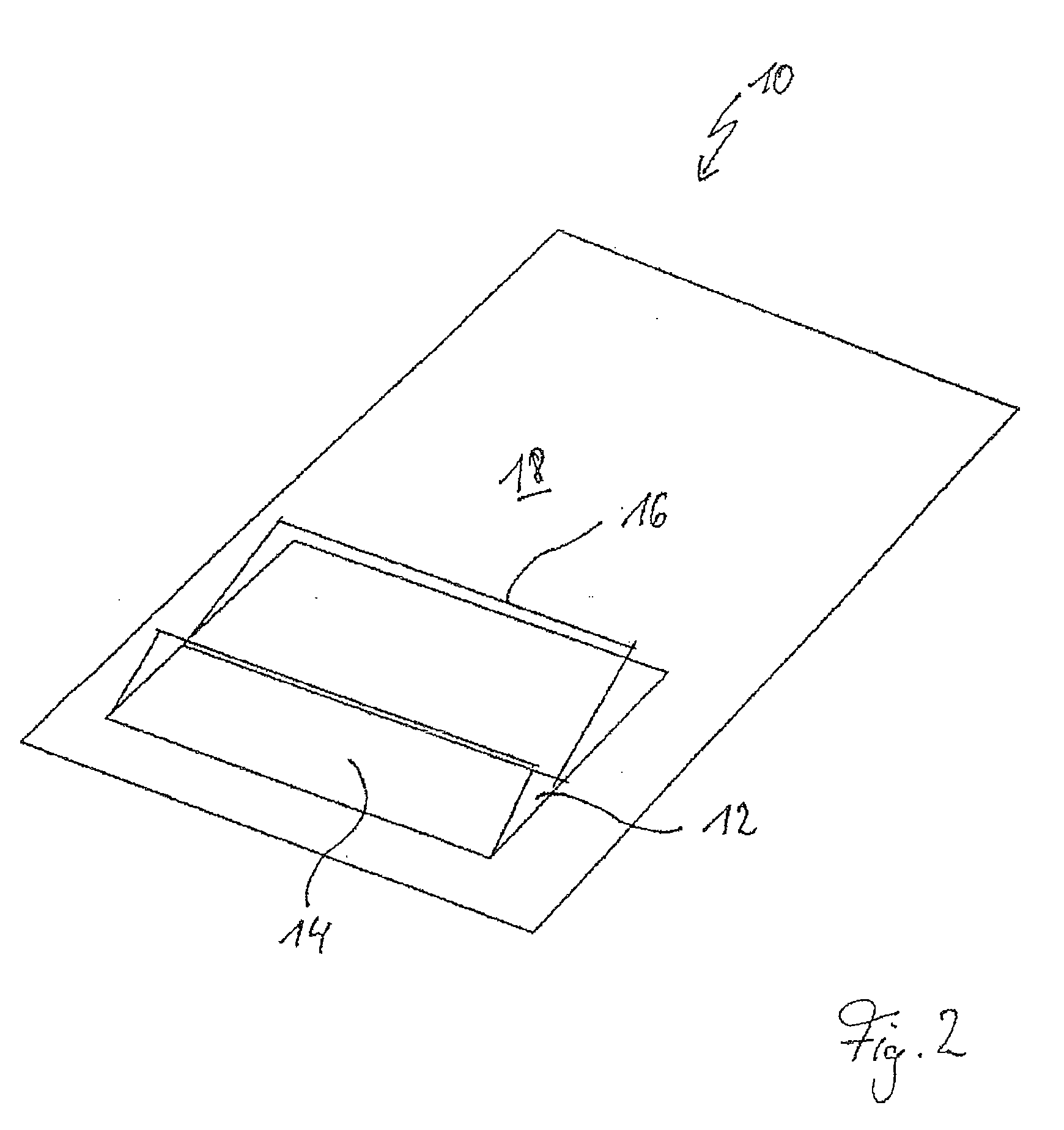
[0045]The drawing illustrates a vehicle roof 10 which is provided with a roof opening 12 which can optionally be closed or at least partially opened up by means of a cover element 14 which is in front in the direction of travel and a cover element 16 which is at the rear in the direction of travel. The two cover elements 14 and 16 can take up different positions. Starting from the closed position of the two cover elements 14 and 16 that is illustrated in FIG. 1, an arrangement of the two cover elements 14, 16 can be realized, in which the two cover elements 14, 16 are deployed and consequently take up a “ventilation position”. This ventilation position, which is also called twin-vent position, is illustrated in FIG. 2. Furthermore, an arrangement can be realized, in which only the front cover element 14 is deployed and is therefore in the ventilation position, whereas the rear cover element 16 is closed. This arrangement of the cover elements 14, 16 can be seen in FIG. 3.

[0046]As ca...


PUM


Abstract

The invention relates to a vehicle roof with two cover elements, a front one of which can be deployed and a rear one of which serves as the sliding cover can be lowered under the stationary vehicle roof and displaced. An embodiment of the invention relates to an actuating mechanism of a drive slide which interacts with a deployment lever in order to swivel the front cover element, said lever being hinged to a support of the front cover element. The deployment movement of the deployment lever is supported by a spring. According to another aspect of the invention, the actuating mechanism comprises a slide unit which comprises one control track each for the front cover element and for the rear cover element. The control tracks are configured in such a manner that the displacement of the slide unit in the direction of the vehicle roof, starting from a closed position of both cover elements, first results in both cover elements being deployed, a continuous displacement of the slide unit in the same direction results in the rear cover element being swung back and lowered and in the rear cover element being retracted.

Description

CROSS-REFERENCE TO RELATED APPLICATIONS[0001]This is a divisional application of U.S. application Ser. No. 12 / 066,295, filed on Jun. 20, 2008, as the National Phase of International Application No. PCT / DE2006 / 001587, filed Sep. 8, 2006, and claims priority from German Patent Application No.: DE 10 2005 043 019.8, filed Sep. 9, 2005, the complete disclosures of the aforesaid applications are incorporated herein by reference.BACKGROUND OF THE INVENTION[0002]1. Field of the Invention[0003]The invention relates to a vehicle roof with at least two cover elements which optionally close or at least partially open up a roof opening, according to the precharacterizing clause of patent claim 1 and of patent claim 8.[0004]2. Description of Related Art[0005]A vehicle roof of this type is known from EP 0 727 331 B1. In this vehicle roof, the front cover element serves as a wind deflector and the rear cover element serves as a sliding cover. The front cover element can be deployed with its rear e...

Claims


Application Information

Patent Timeline
Patent Type & Authority Applications(United States)
IPC IPC(8): B60J7/05
CPCB60J7/22B60J7/053B60J7/043B60J7/057B60Y2200/11
Inventor DE JONG, CHRIS
Owner WEBASTO AG
Why Eureka
Try Eureka