Method and apparatus for detecting hold condition on an acoustic touch surface

a technology of acoustic touch surface and hold condition, which is applied in the field of touch sensitive systems, can solve the problems that no conventional bending wave touch system, however, can identify hold conditions

Active Publication Date: 2011-02-03
ELO TOUCH SOLUTIONS INC +1
View PDF7 Cites 80 Cited by
  • Summary
  • Abstract
  • Description
  • Claims
  • Application Information

AI Technical Summary

Benefits of technology

[0007]In one embodiment, a bending wave touch system includes at least one sensor and a controller. The at least one sensor is coupled to a substrate and is responsive to vibrations in the substrate. The at least one sensor outputs signals. The controller receives the signals from the at least one sensor and identifies touch coordinates based on high frequency components of the signals when a touch on the substrate includes at least one of a tap, a drag and a lift-off. The controller identifies a status of a hold condition of the touch based on at least two different time averages of low frequency components of the signals.
[0008]In another embodiment, a method for identifying a hold condition on a bending wave touch panel includes detecting signals with at least one sensor bonded with a substrate. The signals are indicative of vibrations on the substrate of a bending wave touch panel. At least one of a tap and a drag are identified based on the signals. Two different time averages are calculated based on low frequency components of the signals and a hold condition following the at least one of the tap and the drag is identified based on amplitude levels of the two different time averages.

Problems solved by technology

None of the conventional bending wave touch systems, however, can identify a hold condition, wherein the user has touched the touchscreen and is holding the finger or other object at the same (X,Y) coordinate location.
Unless the user is tapping, dragging or otherwise moving the finger on the surface, bending wave signals in the kilohertz range are not generated and the system does not know that the finger is present on the surface.

Method used


Image

  • Method and apparatus for detecting hold condition on an acoustic touch surface
  • Method and apparatus for detecting hold condition on an acoustic touch surface
  • Method and apparatus for detecting hold condition on an acoustic touch surface

Examples


Embodiment Construction

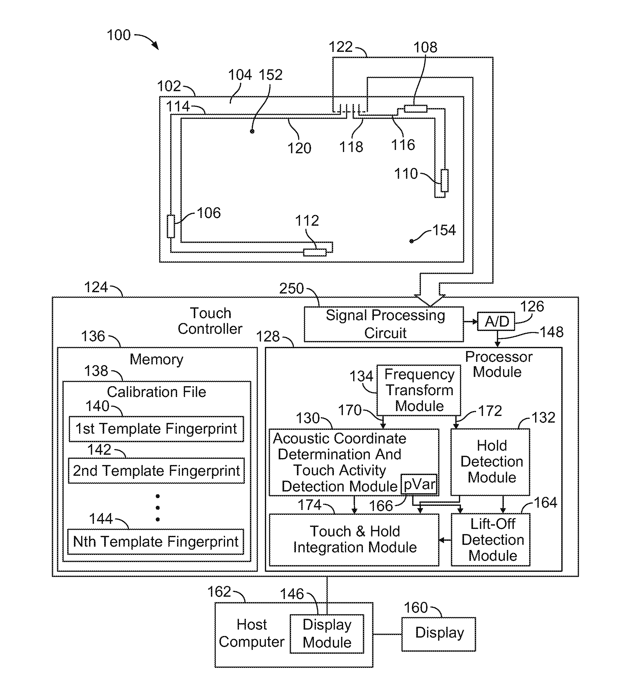
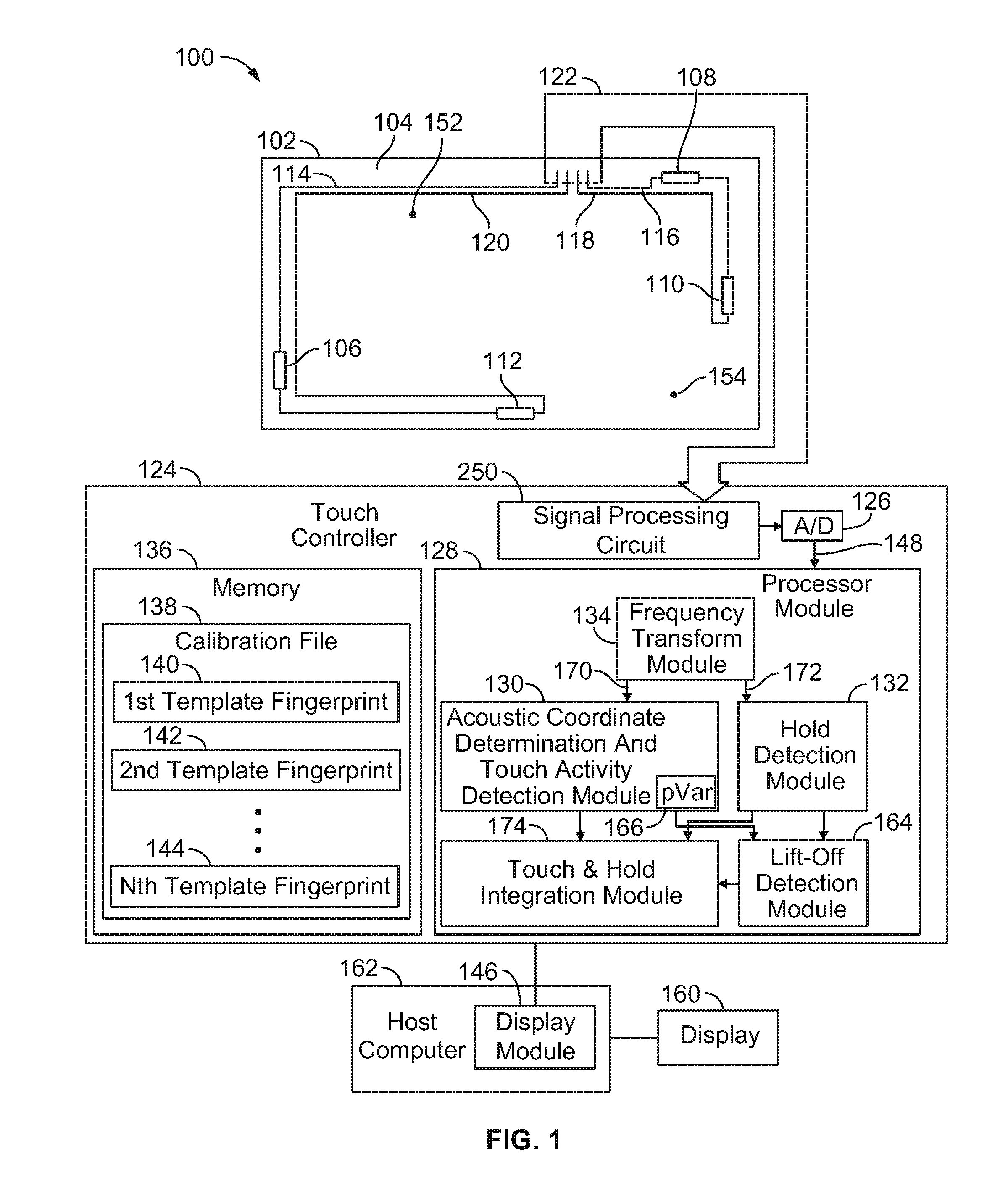
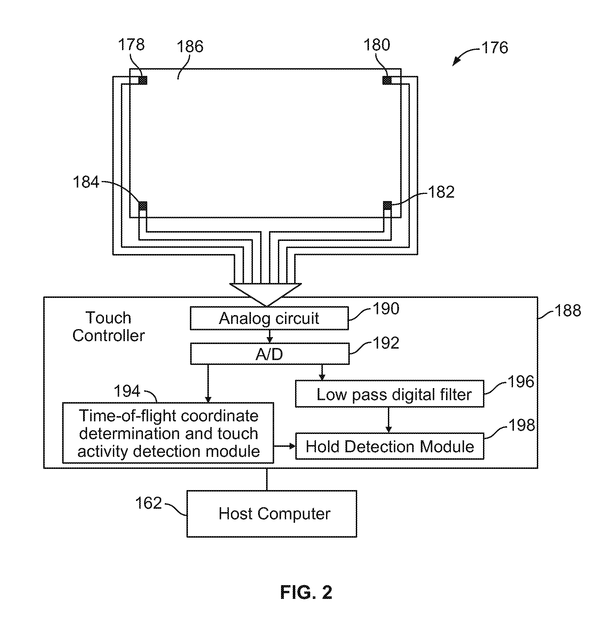
[0026]The foregoing summary, as well as the following detailed description of certain embodiments of the present invention, will be better understood when read in conjunction with the appended drawings. To the extent that the figures illustrate diagrams of the functional blocks of various embodiments, the functional blocks are not necessarily indicative of the division between hardware circuitry. Thus, for example, one or more of the functional blocks (e.g., processors or memories) may be implemented in a single piece of hardware (e.g., a general purpose signal processor or random access memory, hard disk, or the like). Similarly, the programs may be stand alone programs, may be incorporated as subroutines in an operating system, may be functions in an installed software package, and the like. Further, it should be understood by one skilled in the art that many processing steps may be accomplished by either analog circuitry or by numerical digital processing. It should be understood...


PUM


Abstract

A bending wave touch system includes at least one sensor and a touchscreen controller. The at least one sensor is coupled to a substrate and is responsive to vibrations in the substrate. The at least one sensor outputs signals. The controller receives the signals from the at least one sensor and identifies touch coordinates based on high frequency components of the signals when a touch on the substrate includes at least one of a tap, a drag and a lift-off. The controller identifies a status of a hold condition of the touch based on at least two different time averages of low frequency components of the signals.

Description

CROSS REFERENCE TO RELATED APPLICATIONS[0001]This application claims priority from U.S. provisional patent application No. 61 / 180,642 filed May 22, 2009, the content of which is hereby incorporated by reference.BACKGROUND OF THE INVENTION[0002]The subject matter disclosed herein relates generally to touch sensitive systems, and more particularly to determining whether a touch is being held on a bending wave touch panel of a touch sensitive system.[0003]Touch panels are used to provide two-dimensional coordinate information. One example may be an opaque track pad while another example may be a transparent touchscreen placed in front of a display such as a liquid crystal display. Touch panels may be based on a variety of touch technologies including four-wire and five-wire resistive, capacitive, infrared and surface acoustic wave types, as well as bending wave touch technologies.[0004]Bending waves may also be referred to as “flexural waves” as well as “lowest order anti-symmetric Lam...

Claims


Application Information

Patent Timeline
Patent Type & Authority Applications(United States)
IPC IPC(8): G06F3/043
CPCG06F3/043
Inventor SHEIKHZADEH NADJAR, HAMIDBABB, JOE HENRYBRENNAN, ROBERT L.HAUNGS, STEVEN W.WYNNE, JR., JAMES R.KENT, JOEL C.
Owner ELO TOUCH SOLUTIONS INC
Why Eureka
Try Eureka