LED illuminating device

a technology of led illuminating and light-emitting diodes, which is applied in the direction of semiconductor devices for light sources, lighting and heating apparatus, and light support devices. it can solve the problems that conventional heat dissipation devices, such as heat sinks made entirely of extruded aluminum blocks, cannot meet the requirements of heat dissipation

Inactive Publication Date: 2011-02-03
FU ZHUN PRECISION IND SHENZHEN +1
View PDF7 Cites 35 Cited by
  • Summary
  • Abstract
  • Description
  • Claims
  • Application Information

AI Technical Summary

Problems solved by technology

Conventional heat dissipation devices, such as heat sinks made entirely of extruded aluminum blocks, can no longer satisfy the heat dissipation requirement of the high brightness ...

Method used


Image

  • LED illuminating device
  • LED illuminating device
  • LED illuminating device

Examples


Embodiment Construction

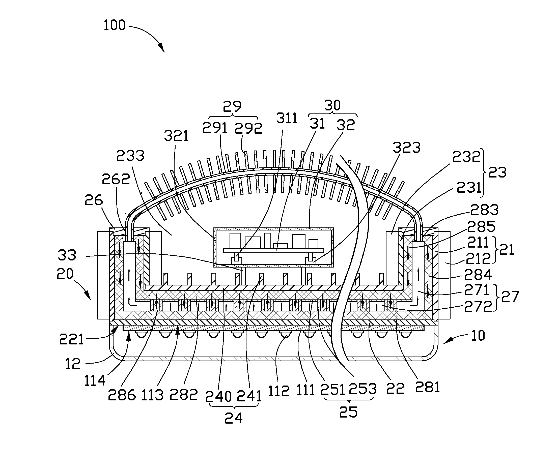
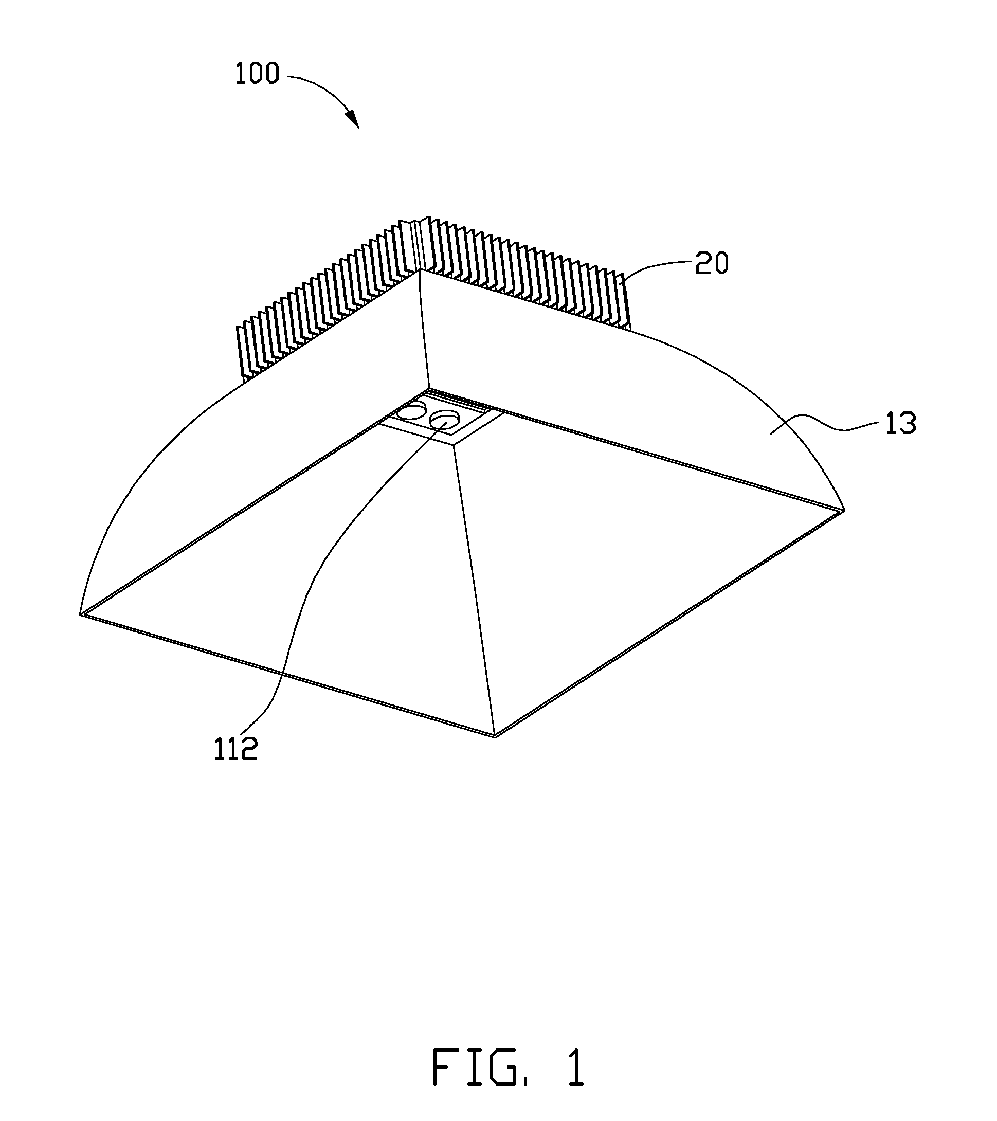
[0013]Referring to FIGS. 1 and 2, an LED illuminating device 100 according to a first embodiment includes an optical module 10, a heat dissipation module 20, and an electric module 30.

[0014]The optical module 10 is arranged at a bottom side of the heat dissipation module 20. The optical module 10 includes a substrate 111, a plurality of LEDs 112, a lens 12, and a cover 13. The cover 13 is hollow. A top end of the cover 13 is connected to an outer periphery of the bottom side of the heat dissipation module 20. The cover 13 expands downwardly, and thus has a cross section gradually increased along a top-to-bottom direction. The substrate 111, the LEDs 112 and the lens 12 are received in the cover 13, and thus are prevented from being contaminated by dust. The substrate 111 is flat, and has a planar top surface 113 attached to the heat dissipation module 20 and an opposite planar bottom surface 114. The LEDs 112 are fixed on the bottom surface 114 of the substrate 111 with emitting sid...


PUM


Abstract

An LED illuminating device includes a boiling room, an optical module, a heat insulating member and a heat exchanging member communicating with the boiling room. The boiling room defines a horizontal room and an annular, vertical room having a bottom end surrounding the horizontal room. A wick structure is received in the boiling room. Working fluid is received in the boiling room and saturated in a bottom portion of the wick structure. The optical module includes a plurality of LEDs attached to a heat absorbing member connecting with the bottom portion of the wick structure. The heat insulating member is received in the boiling room and attached to a middle portion of the wick structure for thermally insulating the middle portion of the wick structure from vaporized working fluid in the horizontal room of the boiling room.

Description

BACKGROUND[0001]1. Technical Field[0002]The disclosure generally relates to light emitting diode (LED) illuminating devices, and particularly to an LED illuminating device with a high heat dissipating efficiency.[0003]2. Description of Related Art[0004]Presently, LEDs (light emitting diodes) are preferred for use in LED illuminating devices rather than CCFLs (cold cathode fluorescent lamps) due to a high brightness, a long lifespan, and a wide color range of the LED.[0005]For an LED, eighty percents to ninety percents of the power consumed by the LED is converted into thermal energy, while only ten percents to twenty percents of the power consumed by the LED is converted into light. In addition, a plurality of LEDs are generally packaged in a single LED illuminating device in order to obtain a desirable illumination brightness. Conventional heat dissipation devices, such as heat sinks made entirely of extruded aluminum blocks, can no longer satisfy the heat dissipation requirement o...

Claims


Application Information

Patent Timeline
IPC IPC(8): F21V29/00
CPCF21V29/004F21V29/006F21Y2101/02F21Y2105/001F21V23/008F21Y2111/001F21V29/777H01L2924/0002F21V29/773F21V29/71F21V29/76F21V29/763H01L2924/00F21Y2105/10F21Y2115/10F21Y2107/00F21V29/51
Inventor LIU, TAY-JIANZHOU, TAO-PINGXIONG, YING
Owner FU ZHUN PRECISION IND SHENZHEN
Why Eureka
Try Eureka