
Method for matching colors between two systems

a color matching and color technology, applied in the field of color metrology, can solve the problems of difficulty in ensuring the appearance of white/gray balance and accurate appearance of other critical regions of color such as skin tones, and inability to achieve the same level of standardization for soft proofing

Active Publication Date: 2011-02-03
EASTMAN KODAK CO
View PDF11 Cites 18 Cited by
  • Summary
  • Abstract
  • Description
  • Claims
  • Application Information

AI Technical Summary

Benefits of technology

The present invention is a color processing system that uses an improved method of defining human observer functions by measuring spectral values for color stimuli and calculating tristimulus values. The system takes into account the spectral power distribution of the color stimulus, resulting in better matches between different systems. The invention also includes methods for matching colors and reproducing colors on imaging devices. The technical effects of the invention include better visual match between systems with different spectral characteristics, reduced impact of narrow band properties of RGB primaries, and improved color appearance on devices with significant color differences.

Problems solved by technology

Although existing CIE and ISO standards appear to work well for multiple prints viewed under the same illumination, achieving the same level of standardization for soft proofing has proven to be more challenging.
However, it has been observed that it is difficult to ensure both accurate appearance of white / gray balance and accurate appearance of other critical regions of color such as skin tones.
For critical color requirements, however, there can exist unacceptable visual differences between display and hard copy in skin tones (for example) that equate to several percentage points of change in magenta dot gain.
Although this error is small, it is enough to be problematic for critical work.

Method used


Image

  • Method for matching colors between two systems
  • Method for matching colors between two systems
  • Method for matching colors between two systems

Examples


example mathematical

Approaches for Calculating NSHOF

[0051]1. Linear Combination of Two Static Sets of x(λ) y(λ) z(λ)

[0052]A first example defines two sets of human observer functions, one determined using the saturation method and one defined using the Maxwell method (indicated by subscripts S and M respectively). A weighted combination of the two functions yields:

xyzC(λ)=α({right arrow over (XYZ)}s) xyzS(λ)+(1.0−α({right arrow over (XYZ)}S)) xyzM(λ)   (Eq. 6)

[0053]The weighting factor α(XYZs) indicates magnitude of saturation and should approach 1 for saturated colors and approach 0 for neutral colors. Note that for most of these approaches, two integrations will need to be performed, one for calculating XYZs followed by a second integration to calculate XYZc from the above corrected human observer function. An example of a “reasonable” definition for α(XYZs) is:

α(XYZs)=⌊max(XSXW,YSYW,ZSZW)-min(XSXW,YSYW,ZSZW)⌋max(XSXW,YSYW,ZSZW)(Eq.7)

[0054]where XYZW is the tristimulus XYZ value of the reference whi...

example 1

Method for Characterizing a Color in Terms of Tristimulus Values

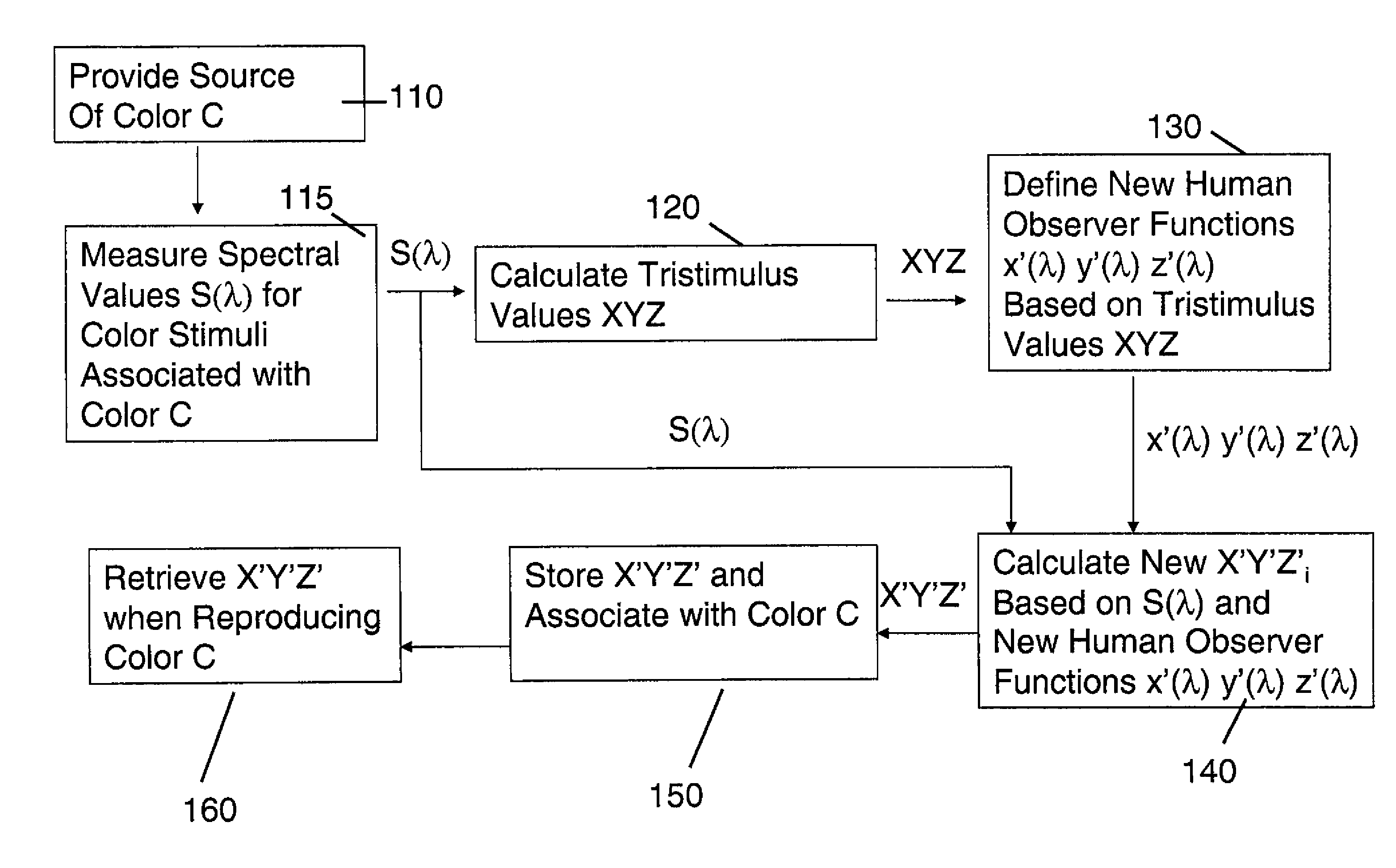
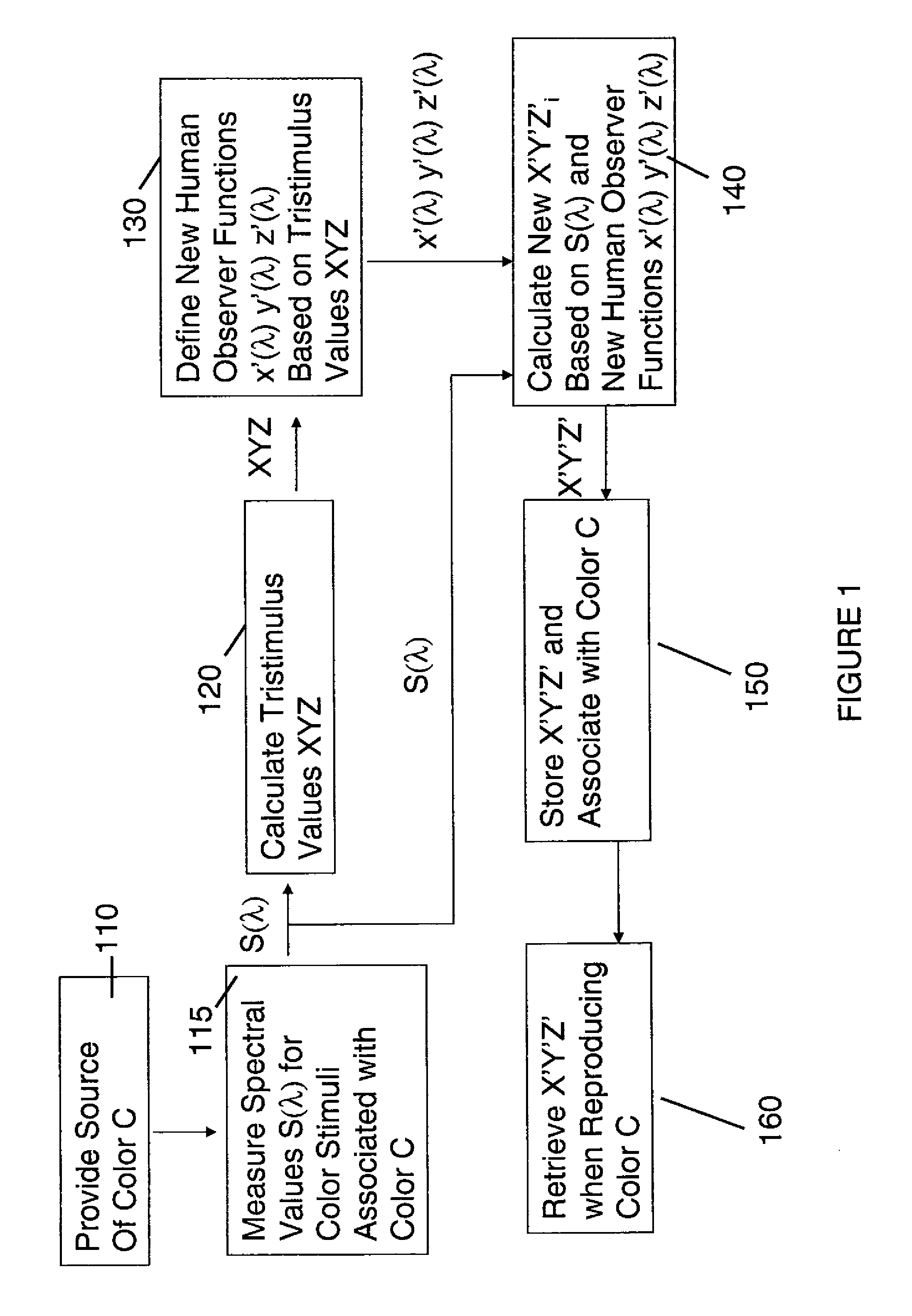
[0079]The first example with a color measurement and characterization method indicated is shown in FIG. 1. Step 110 indicates that a source of color C is provided, which is measured and characterized. This color may be a reflective material viewed in an illumination system, a region of color rendered on a display, or a region of color projected with a digital projector. The spectral power distribution S(λ) of the color stimulus is measured at step 115 with a spectral measurement device such as a spectrophotometer controlled by a processing system.

[0080]For emissive devices, an emissive spectrophotometer is used to measure S(λ) directly. In the case of reflective material in a lightbox, it is possible to measure S(λ) directly. However, it is more common for the spectrophotometer to illuminate the reflective material with a know built-in illumination, infer from the measurement the reflectance spectrum R(λ) of the materia...

example 2

Method for Matching Colors

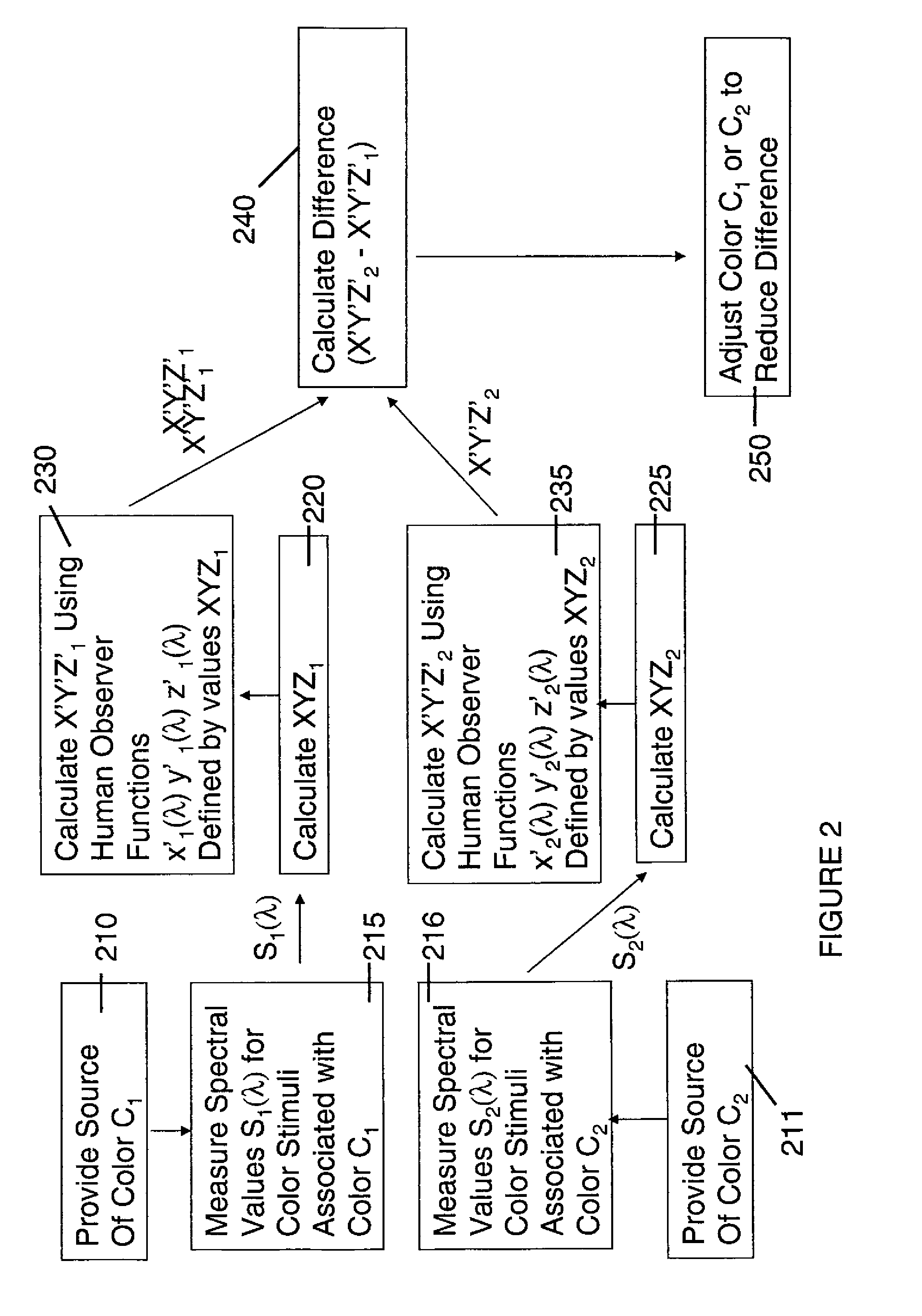
[0084]The next example, describes a method for matching two colors indicated in FIG. 2. A source of color C1 which is measured and characterized at step 210. This color may be a reflective material viewed in an illumination system, a region of color rendered on a display, or a region of color projected with a digital projector. In step 215, the spectral power distribution S1(λ) of the color stimulus is measured with a spectral measurement device such as a spectrophotometer controlled by a processing system as described in Example 1.

[0085]In step 220, the tristimulus values XYZ1 are calculated, for example using current human observer functions x(λ) y(λ) z(λ) determined from the saturation method of color matching. In step 230, the values of XYZ1 are used to define a new set of human observer functions x′(λ) y′(λ) z′(λ), for example using Equation 6 above, which are combined with S1(λ) to generate revised tristimulus values X′Y′Z′1.

[0086]In step 211 the proc...


PUM


Abstract

A method for matching colors including comparing the appearance of a first white color associated with a first color imaging system and a second white color associated with a second color imaging system, wherein the tristimulus values of the first and second white color are similar; determining a fixed correction to the tristimulus values of the second white color to achieve a visual match to the first white color; measuring a first set of spectral values for a first color associated with the first color imaging system; determining a first set of tristimulus values from the first set of spectral values; measuring a second set of spectral values for a second color associated with the second color imaging system; determining a second set of tristimulus values from the second set of spectral values; applying a correction to the tristimulus values of the second color; determining a difference between the tristimulus value of the first color and the corrected tristimulus value of the second color; and adjusting the second color to reduce the difference.

Description

CROSS REFERENCE TO RELATED APPLICATIONS[0001]Reference is made to commonly-assigned copending U.S. patent application Ser. No. ______ (Attorney Docket No. 95734 / NAB), filed herewith, entitled A METHOD FOR CONVERTING DIGITAL COLOR IMAGES, by Christopher Edge; U.S. patent application Ser. No.______ (Attorney Docket No. 95775 / NAB), filed herewith, entitled METHOD FOR MATCHING COLORS, by Christopher Edge; U.S. patent application Ser. No. ______ (Attorney Docket No. 95776 / NAB), filed herewith, entitled METHOD FOR CHARACTERIZING THE COLOR RESPONSE OF AN IMAGING DEVICE, by Christopher Edge; U.S. patent application Ser. No. ______ (Attorney Docket No. 95777 / NAB), filed herewith, entitled METHOD FOR REPRODUCING AN IMAGE ON AN IMAGING DEVICE, by Christopher Edge; and U.S. patent application Ser. No. ______ (Attorney Docket No. 95778 / NAB), filed herewith, entitled METHOD AND APPARATUS FOR MEASURING COLORS, by Christopher Edge; the disclosures of which are incorporated herein.FIELD OF THE INVEN...

Claims


Application Information

Patent Timeline
Patent Type & Authority Applications(United States)
IPC IPC(8): G06K9/00
CPCG06K9/00H04N1/6052G01J3/462G01J3/463G01J3/465G01J3/506
Inventor EDGE, CHRISTOPHER J.
Owner EASTMAN KODAK CO
Learn More