Pipe guide adapter

a technology of adapters and pipe guides, which is applied in the direction of measuring devices, instruments, printing, etc., can solve the problems that the gate member having a first diameter is not suitable for supporting the vertical gate member having a second diameter

Active Publication Date: 2011-02-10
MUELLER FREDERICK HAROLD +2
View PDF7 Cites 17 Cited by
  • Summary
  • Abstract
  • Description
  • Claims
  • Application Information

AI Technical Summary

Benefits of technology

[0007]The pipe guide adapter includes one or more adapter marking slots formed on the body sections for marking the pipe. The adapter marking slots are formed by creating openings through the marking secti...

Problems solved by technology

Thus, a saddle-shaped pattern which supports a horizontal gate member having a fi...

Method used


Image

  • Pipe guide adapter
  • Pipe guide adapter
  • Pipe guide adapter

Examples


Embodiment Construction

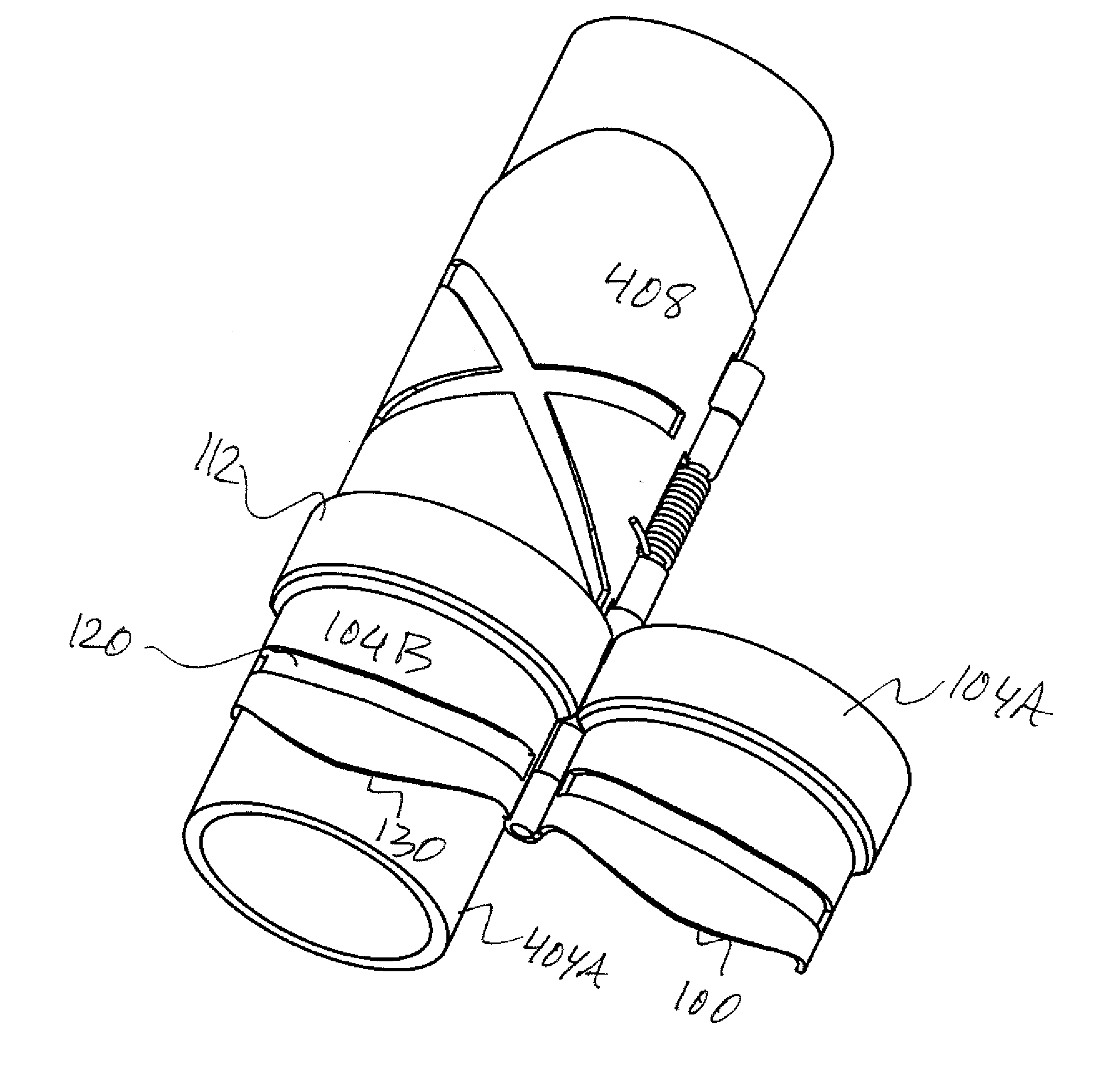
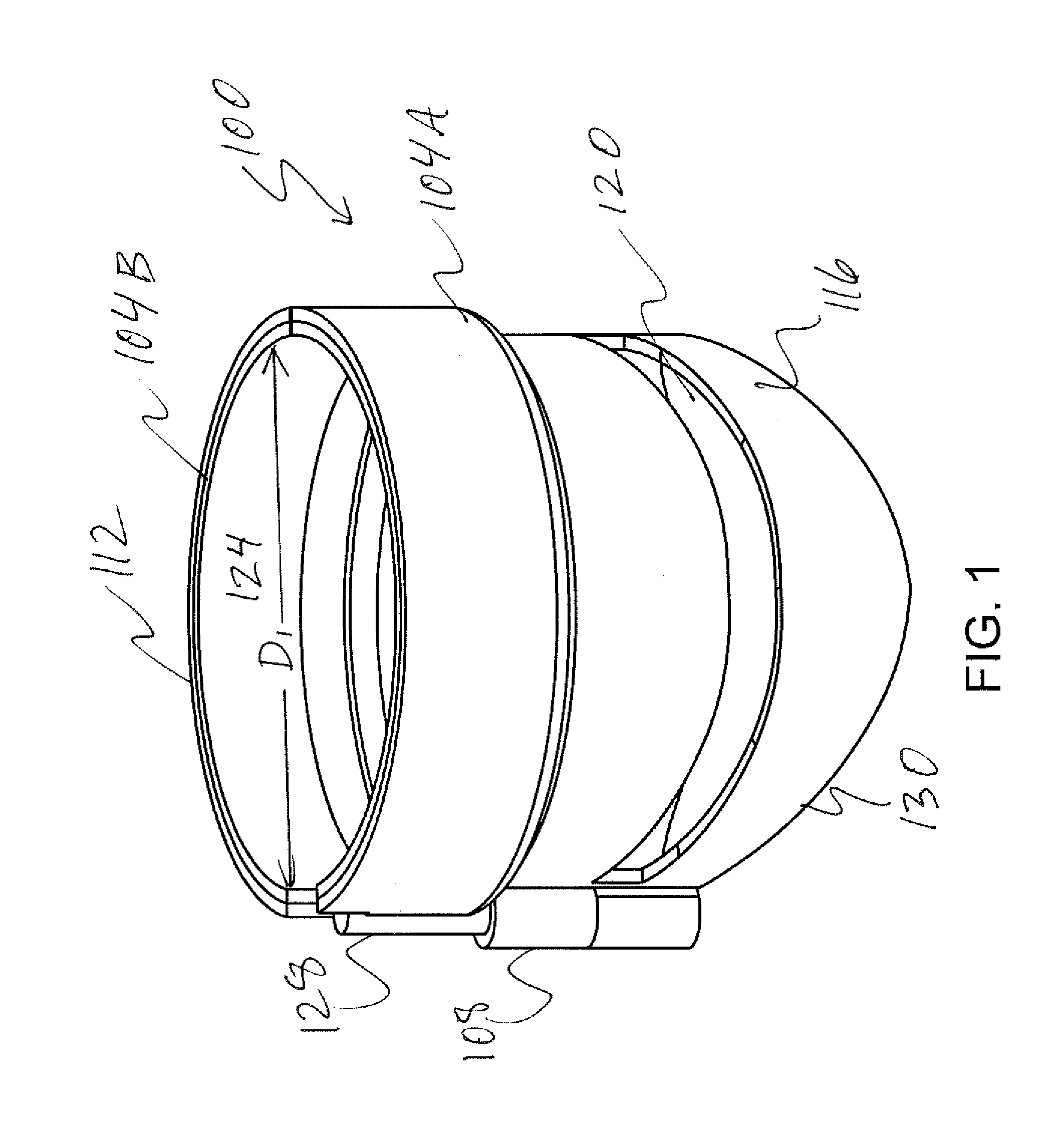
[0016]FIG. 1 illustrates a pipe guide adapter 100 in accordance with one embodiment. The pipe guide adapter 100 is configured to add marking slots and marking edges to a pipe guide (not shown in FIG. 1).

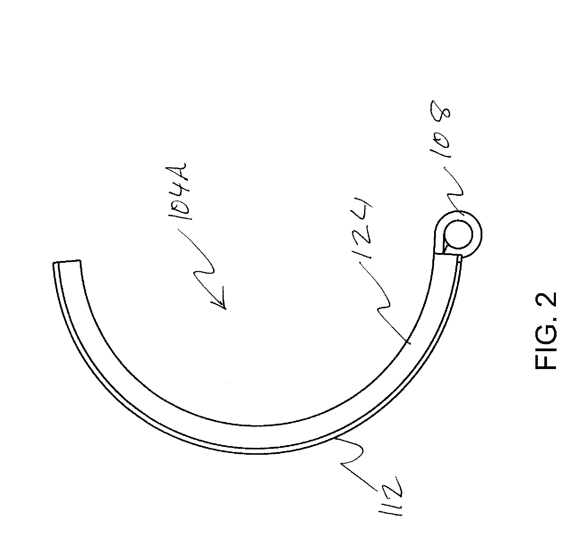
[0017]The pipe guide adapter 100 includes body sections 104A and 104B. The body sections 104A and 104B are joined by a hinge 108, which enables the pipe guide adapter 100 to be in open and closed positions. The body sections 104A and 104B each have a gripping end 112 and a marking section 116. The gripping end 112 has a diameter D1 greater than the diameter of the pipe guide to circumferentially grip a portion of the pipe guide in the closed position and to attach to the pipe guide. The pipe will be circumferentially gripped jointly by the pipe guide and the pipe guide adapter 100.

[0018]The body sections 104A and 104B each include one or more adapter marking slots 120 for marking the pipe. The adapter marking slots 120 are formed by creating openings through the marking section 116.

[...


PUM


Abstract

A pipe guide adapter adds marking slots and marking edges to a pipe guide. The pipe guide adapter includes two body sections joined by a hinge enabling the pipe guide adapter to be in open and closed positions. The body sections each include a gripping end and a marking section. The gripping end has a diameter greater than the diameter of the pipe guide to circumferentially grip a portion of the pipe guide in the closed position and to attach to the pipe guide. A pipe is circumferentially gripped jointly by the pipe guide and the pipe guide adapter. A hinge pin is partially disposed in the hinge and extends beyond the hinge. The hinge pin allows tie pipe guide adapter to be aligned to the pipe guide. The extended portion of the hinge pin acts as a stop and a spacer between the pipe guide adapter and the pipe guide.

Description

FIELD OF THE INVENTION[0001]This invention relates to pipe marking and cutting tools, and more specifically relates to a pipe guide adapter for marking and cutting tools.BACKGROUND OF THE INVENTION[0002]Pipe Guides are used to mark pipes in different patterns and angles prior to the pipes being cut. A pipe guide is wrapped around the pipe and a marking chalk or pen is used to mark the pipe. The pipe guide is thereafter removed and the pipe is cut along the mark.[0003]Existing pipe guides may have a flat edge, an angular edge or a saddle-shaped pattern. Existing pipe guides may also have one or more marking slots formed at a particular angle. The marking slots are made by openings in the pipe guide body. The flat edge may be used to mark the pipes at a 90 degree angle to construct a flat top fence. The angular shaped edge may be used to create a fence having an angular top.[0004]The saddle-slipped pattern is often used to cut pipes for a gate. Typically, a vertical gate member of a g...

Claims


Application Information

Patent Timeline
IPC IPC(8): G01B1/00B43L13/00
CPCB43L13/205
Inventor MUELLER, FREDERICK HAROLDLEE, MICHAEL ALVISDIEBOLD, DOUGLAS RAY
Owner MUELLER FREDERICK HAROLD
Why Eureka
Try Eureka