LED assembly

a technology of led components and assemblies, applied in semiconductor devices, lighting and heating apparatus, lighting support devices, etc., can solve the problems of inability to effectively adjust the light generated by the encapsulant, and the inability to adjust the light pattern to meet the illumination demands

Inactive Publication Date: 2011-02-10
FU ZHUN PRECISION IND SHENZHEN +1
View PDF8 Cites 11 Cited by
  • Summary
  • Abstract
  • Description
  • Claims
  • Application Information

AI Technical Summary

Benefits of technology

[0006]However, in assembly of the light-adjusting device, the main body of the light-adjusting device must be accurately mounted over these LEDs of the LED lamp to make sure that each lens is accurately corresponding to one of the LEDs. By doing this, the light-adjusting device adjusts light emitted from the LEDs to form a perfect light pattern. Once assembly errors of the light-adjusting device exist, it is unavoidable that the lenses can not be in alignment with corresponding LEDs, which results in that the adjusted light pattern cannot satisfy the demands of illumination.

Problems solved by technology

However, due to the size limitation of the encapsulant, the encapsulant cannot effectively adjust light generated by the LED die whereby a light pattern of the LEDs cannot satisfy some illumination requirements.
Once assembly errors of the light-adjusting device exist, it is unavoidable that the lenses can not be in alignment with corresponding LEDs, which results in that the adjusted light pattern cannot satisfy the demands of illumination.

Method used


Image

  • LED assembly
  • LED assembly
  • LED assembly

Examples


Embodiment Construction

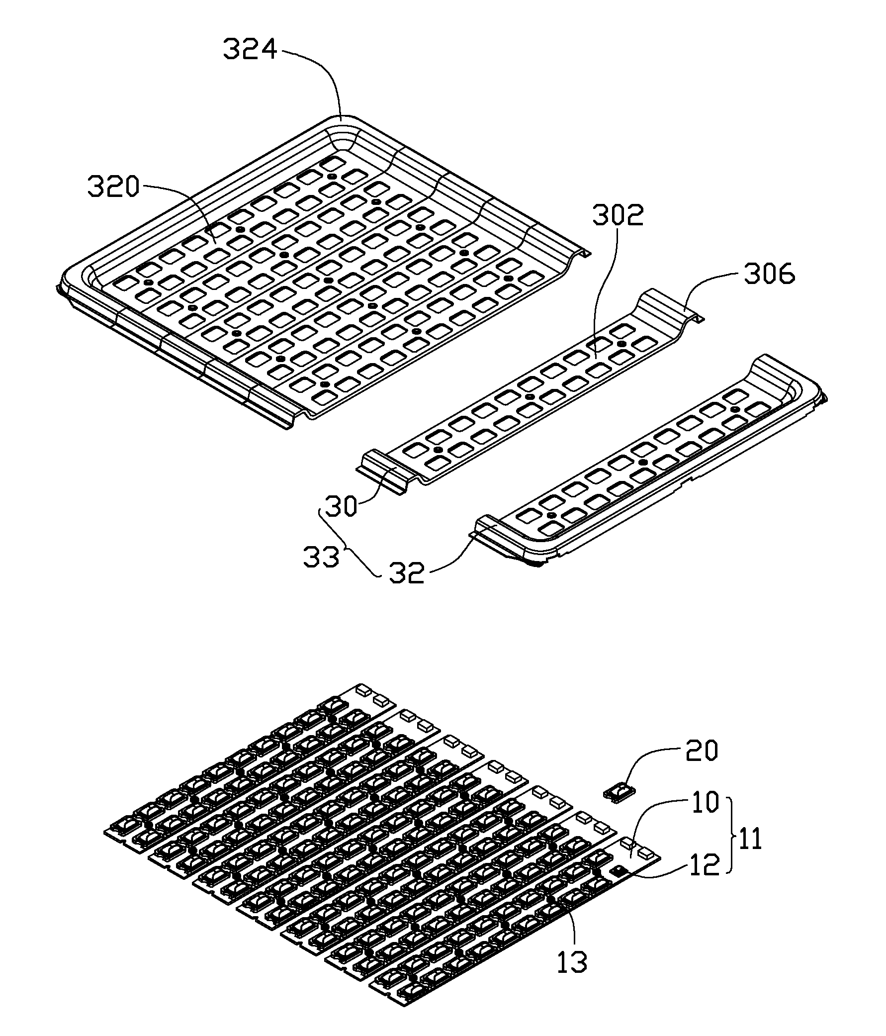
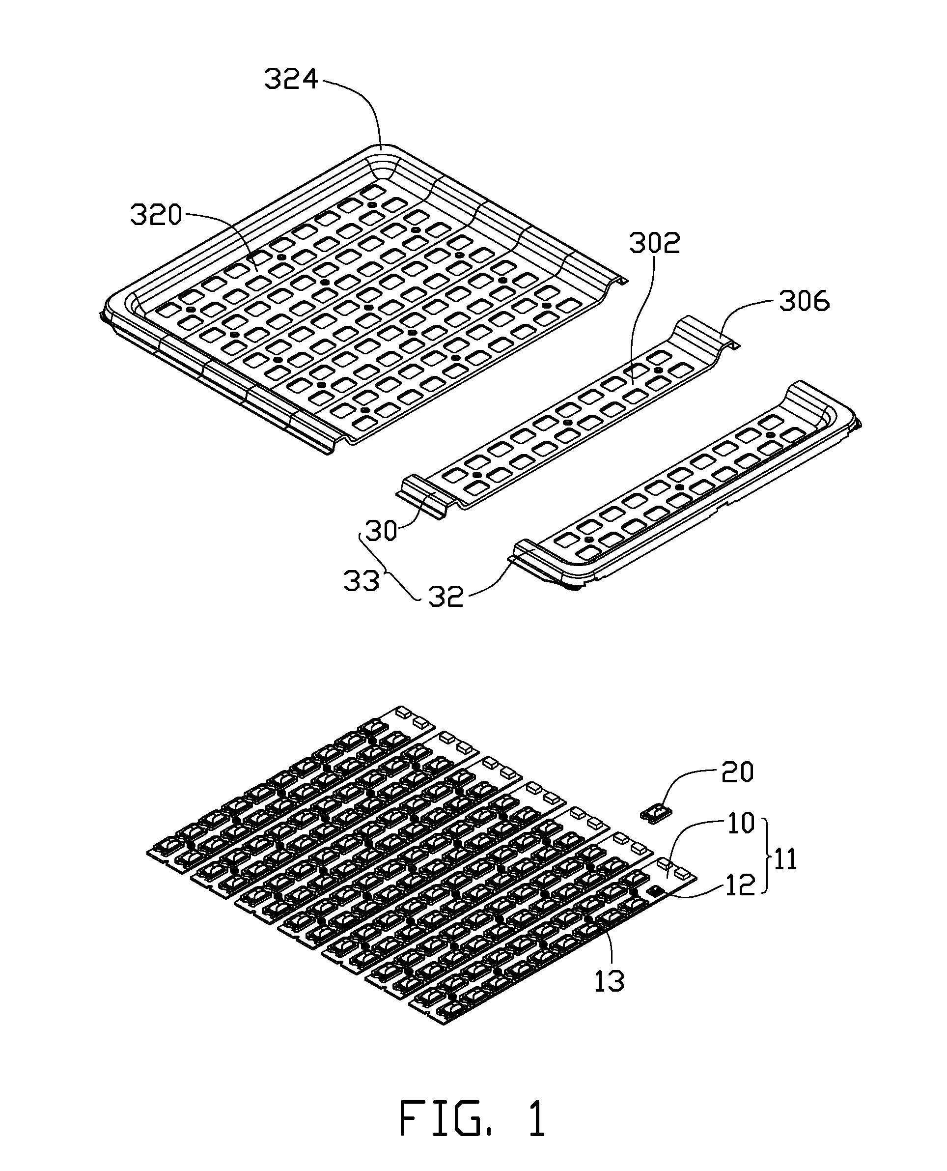
[0014]Referring to FIG. 1, an LED (light emitting diode) assembly is illustrated in accordance with an embodiment of the disclosure. The LED assembly includes a plurality of LED modules 11, a plurality of individual lenses 20 placed on the LED modules 11, and a pressing plate 33 pressing the lenses 20 on the LED modules 11. Each of the LED modules 11 includes a flat, rectangular printed circuit board 10 and a plurality of LEDs 12 attached to a top surface of the printed circuit board 10. An amount of the lenses 20 is identical to that of the LEDs 12. Each lens 20 cooperates with a corresponding LED 12 to adjust light emitted from the corresponding LED 12. The pressing plate 33 presses these lens 20 on the printed circuit boards 10 of the LED modules 11.

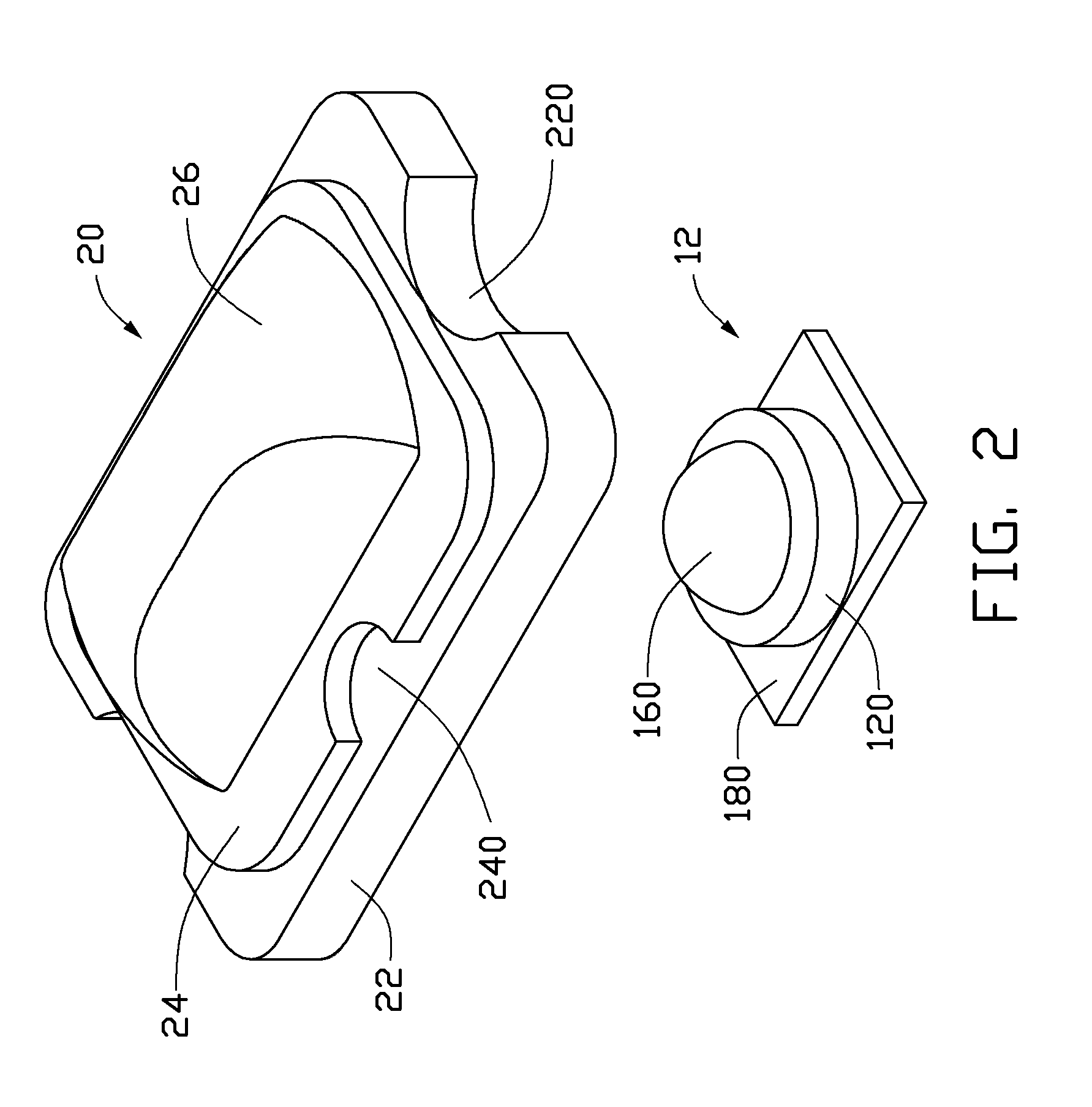
[0015]Also referring to FIG. 2, each LED module 11 is rectangular in shape. The LEDs 12 of each LED module 11 are arranged into two spaced rows along a length direction of the printed circuit board 10. Each LED 12 includes a rectangul...


PUM


Abstract

An LED assembly includes a plurality of LED modules, a plurality of individual lenses and a pressing plate. Each LED module has a printed circuit board and a plurality of LEDs attached to the printed circuit board. Each lens covers a corresponding LED. Each lens includes a supporting base and a light adjusting portion disposed on the supporting portion. The pressing plate defines a plurality of through holes corresponding to the light adjusting portions of the lenses. The lenses cooperates with the LEDs. The light adjusting portions of the lenses extend through the through holes of the pressing plate. The pressing plate presses peripheral portions of the supporting bases towards the printed circuit boards of the LED modules.

Description

BACKGROUND[0001]1. Technical Field[0002]The disclosure relates to an illuminating device and, more particularly, to an LED (light emitting diode) assembly.[0003]2. Description of Related Art[0004]LEDs (light emitting diodes), available since the early 1960's, have been increasingly used in a variety of application fields and are intended to be a high quality replacement for conventional light sources due to high light-emitting efficiency, environmental friendliness, and low power consumption.[0005]A typical LED lamp includes a housing and a plurality of LEDs disposed in the housing. Each of the LEDs includes an LED die and a transparent encapsulant enveloping the LED die for adjusting light emitted from the LED die. However, due to the size limitation of the encapsulant, the encapsulant cannot effectively adjust light generated by the LED die whereby a light pattern of the LEDs cannot satisfy some illumination requirements. Therefore, light-adjusting devices are utilized for further...

Claims


Application Information

Patent Timeline
Patent Type & Authority Applications(United States)
IPC IPC(8): F21V5/00
CPCF21V5/007F21V5/04F21Y2105/001F21Y2101/02F21W2131/103F21Y2105/10F21Y2115/10
Inventor ZHANG, HAI-WEILIU, YI-SANCHEN, CHIN-CHUNG
Owner FU ZHUN PRECISION IND SHENZHEN
Why Eureka
Try Eureka