
Electromagnetic boat speedometer having boundary layer velocity compensation

a speedometer and boundary layer technology, applied in the field of electromagnetical boat speedometers, can solve the problems of affecting the speed measurement, the hull of the boat is prone to repeated fouling, and the speed measurement can be adversely affected by the hull

Active Publication Date: 2016-03-03
BRICKHOUSE INNOVATIONS
View PDF6 Cites 6 Cited by
  • Summary
  • Abstract
  • Description
  • Claims
  • Application Information

AI Technical Summary

Benefits of technology

The invention provides a device that measures the speed of a boat or other watercraft using electromagnetic fields. The device includes two coils, one primary and one secondary, which are placed close to the surface of the boat. The primary coil is larger and placed in a way that it surrounds the secondary coil. The device also includes electrodes that measure the flow of water near the boat. The secondary coil is designed to measure the flow of water that is affected by the boat's hull. The signals from the electrodes are combined in a way that the secondary coil's signals are used to correct the primary coil's signals, resulting in a more accurate measurement of the boat's speed. This device can measure larger volumes of water and can be designed to measure the speed of the boat's cross-flow. The invention also provides a method for removing the effects of the boat's hull on the speed measurement, which can be important for some applications.

Problems solved by technology

Paddle wheels and pitot tubes are prone to repeated fouling by marine growth as well as by debris in the water.
A problem associated with most existing boat speedometers is that the speed measurement is made very close to the hull of the boat and in such a small volume of water that the speed measurement can be adversely effected by the boat's hull, especially at high speeds and on larger boats.

Method used


Image

  • Electromagnetic boat speedometer having boundary layer velocity compensation
  • Electromagnetic boat speedometer having boundary layer velocity compensation
  • Electromagnetic boat speedometer having boundary layer velocity compensation

Examples


Embodiment Construction

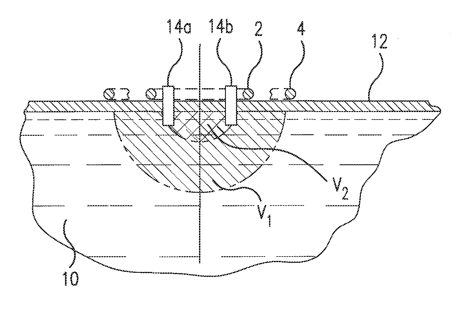
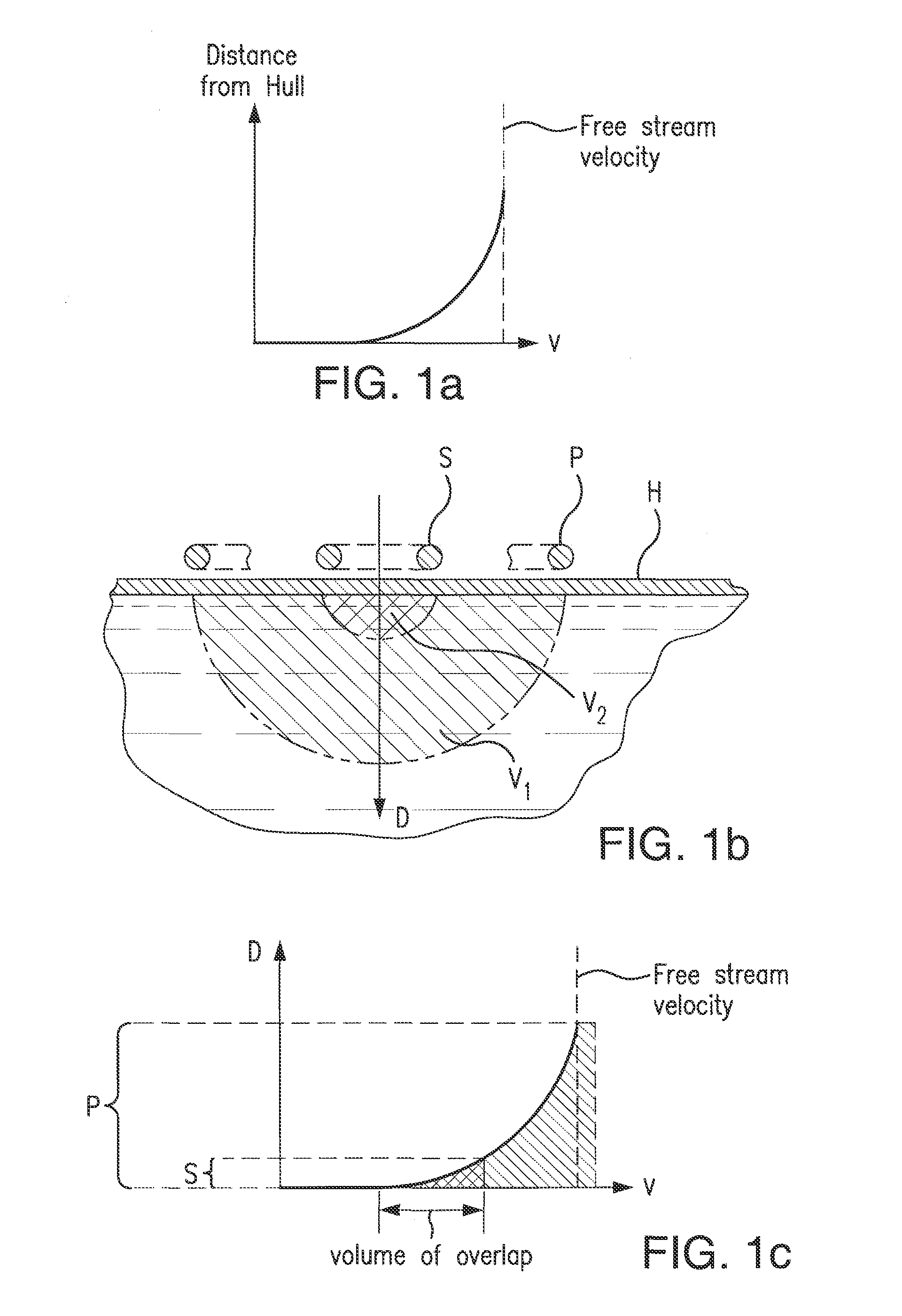
[0037]In accordance with the present invention, velocity measurement correction means are provided for correcting for hull-induced inaccuracies. As shown in FIG. 1a, the velocity V near the hull of a boat varies with distance D from the hull. Note that the velocity at the hull is essentially zero and that as the distance from the hull increases, the velocity slowly increases until eventually it becomes equal to the free stream velocity, where the hull no longer affects the flow. FIG. 1b illustrates the areas of water volume influence V1 of a large primary coil / electrode assembly P relative to a smaller volume portion V2 produced within the larger water portion by a secondary coil / electrode assembly S. As shown in FIG. 1c, these areas of influence are compared with the velocity gradient of the flow in the vicinity of the hull. It is noted that the large coil / electrode assembly includes the flow measured by the small coil / electrode assembly plus an additional volume of flow well beyon...


PUM


Abstract

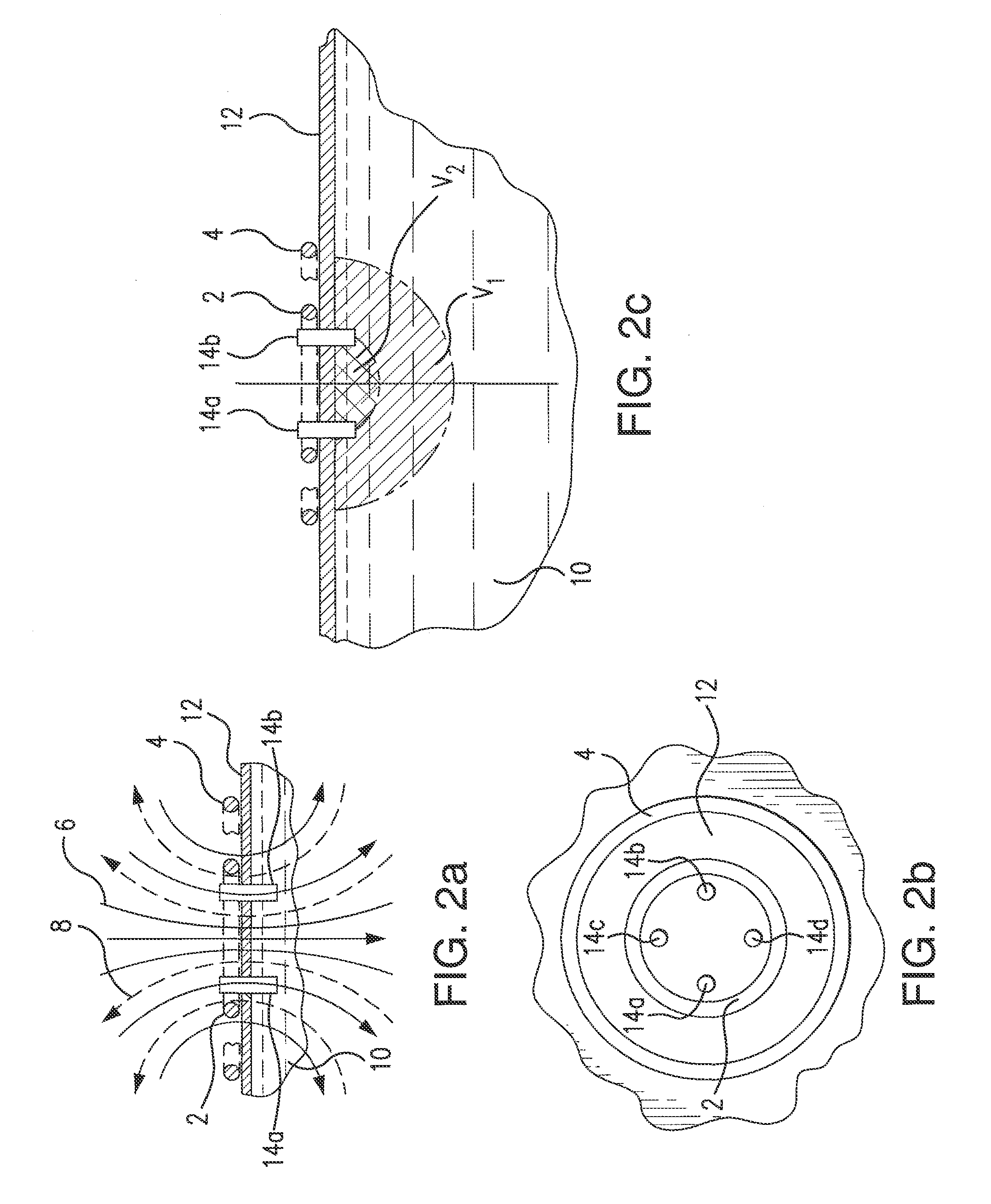
An electromagnetic boat speedometer includes a boundary layer velocity compensating arrangement comprising a primary coil for producing a primary electromagnetic field within a relatively large first volume of water, a secondary coil for producing a secondary electromagnetic field within a relatively small portion of the first volume of water immediately adjacent the hull of the boat, and a set of first electrodes removably mounted in one or more openings in the hull of the boat, such that the tips of the first electrodes extending into the relatively small water portion. In one embodiment, the coils are simultaneously energized in opposition, so that the primary and secondary electromagnetic fields are in opposition. In a second embodiment, the coils are energized alternately, and the signals produced by the electrodes are modified to achieve the desired boundary layer compensation. A second set of second electrodes may be included in the second embodiment.

Description

REFERENCE TO RELATED APPLICATIONS[0001]This application is related to the Marsh application Ser. No. 13 / 935,933 filed Jul. 5, 2013 [Attorneys Case No. 50173], which in turn is a continuation-in-part of the Marsh application Ser. No. 13 / 587,876 filed Aug. 16, 2012 entitled “Electromagnetic Boat Speedometer”, now abandoned [Attorneys Case No. 50109].BACKGROUND OF THE INVENTION[0002]1. Field of the Invention[0003]An electromagnetic boat speedometer includes a boundary layer velocity compensating arrangement comprising a primary coil for producing a primary electromagnetic field within a relatively large first volume of water, a secondary coil for producing a secondary electromagnetic field within a relatively small portion of the first volume of water immediately adjacent the hull of the boat, and a set of first electrodes removably mounted in one or more openings in the hull of the boat, such that the tips of the first electrodes extending into the relatively small water portion. The ...

Claims


Application Information

Patent Timeline
IPC IPC(8): G01P3/50G01D5/20
CPCG01D5/20G01P3/50G01P5/08
Inventor MARSH, LAWRENCE, B.
Owner BRICKHOUSE INNOVATIONS
Learn More