
Apparatus and methods for controlling electron microscope stages

an electron microscope and apparatus technology, applied in the field of electron microscopes, can solve the problems of inability to precisely image individual atoms with clarity, difficulty in manual alignment process, and difficulty in operation of electron microscopes

Active Publication Date: 2015-08-11
RGT UNIV OF CALIFORNIA
View PDF15 Cites 10 Cited by
  • Summary
  • Abstract
  • Description
  • Claims
  • Application Information

AI Technical Summary

Benefits of technology

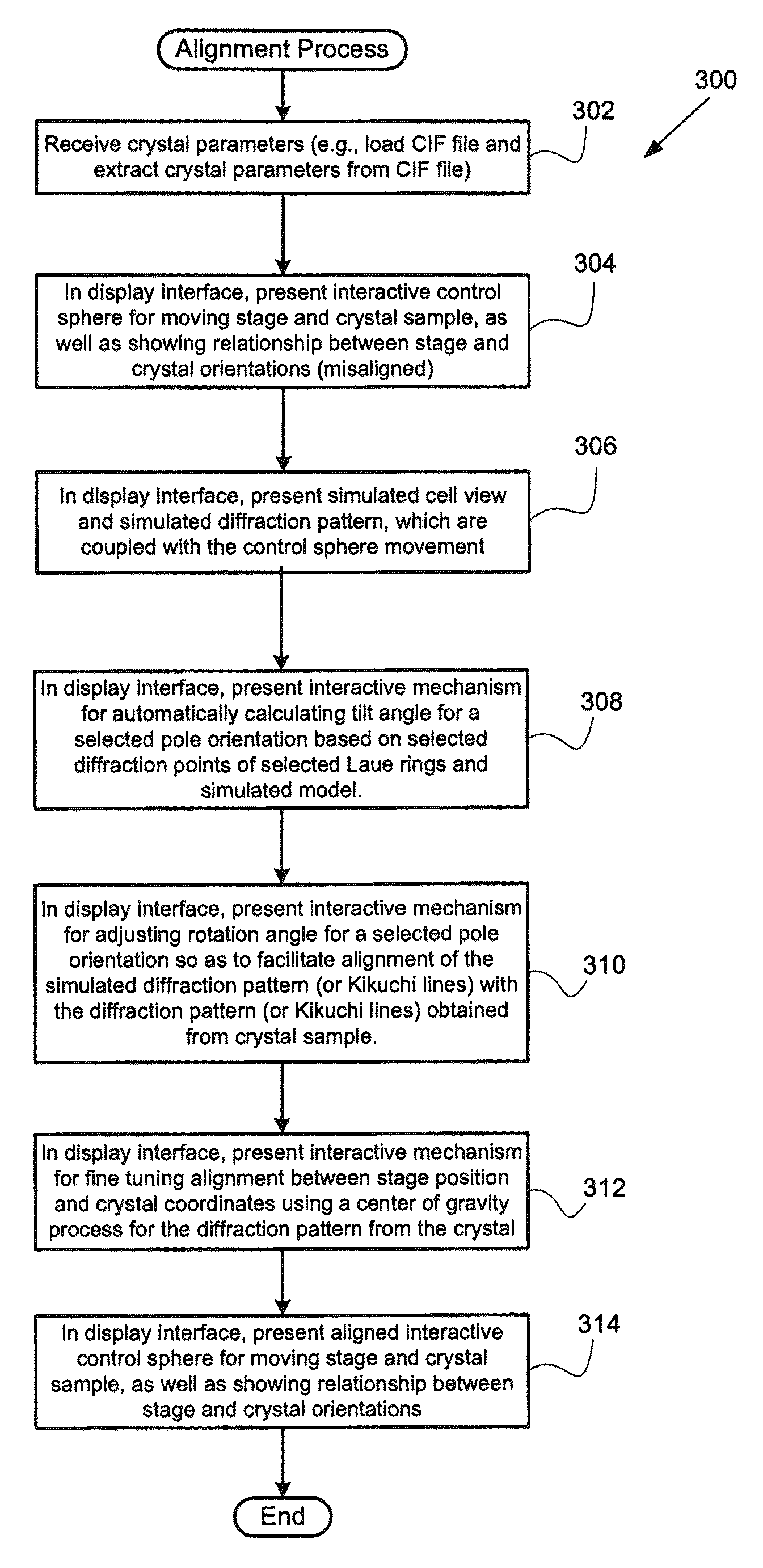
[0009]In a further embodiment, the user alignment process further comprises (i) in the display, presenting an overlay of the simulated diffraction pattern and the actual diffraction pattern, (ii) receiving an adjustment of a rotation position of the crystallographic coordinates with respect to the actual diffraction pattern, wherein the adjustment is accomplished by rotating the simulated diffraction pattern with respect to the actual diffraction pattern to thereby cause alignment of a plurality of crystallographic model coordinates with a plurality of actual crystallographic sample coordinates, (iii) determining a rotation angle relationship between the stage and pole positions based on the received adjustment, (iv) in the display, presenting the actual diffraction pattern and its plurality of different intensity values of diffraction points, (v) receiving a selection of a center and a plurality of non-colinear points of the actual diffraction pattern, and (vi) automatically adjusting the determined rotation relationship based on a center of mass calculation of the different intensity values with respect to the center of the actual diffraction pattern and non-colinear points so as to align the stage and pole positions of the control sphere to thereby accurately correspond with the stage and pole positions of the crystal sample.

Problems solved by technology

An operator of an electron microscope may encounter several challenges when attempting to image a crystalline structure at high resolutions, e.g., so as to resolve individual atoms.
For example, unless the atoms of such a crystalline structure are perfectly aligned relative to the viewing axis so that the atoms in each column that is parallel to such axis are aligned, any misaligned atoms will tend to blur together so that the individual atoms cannot be precisely imaged with clarity.
The efficiency of such manual alignment techniques is highly dependent on the particular expertise of the operator and, additionally, these manual alignment processes tend to be very tedious for the operator.

Method used


Image

  • Apparatus and methods for controlling electron microscope stages
  • Apparatus and methods for controlling electron microscope stages
  • Apparatus and methods for controlling electron microscope stages

Examples


Embodiment Construction

[0025]Reference will now be made in detail to the specific embodiments of the invention. Examples of these specific embodiments are illustrated in the accompanying drawings. While the invention will be described in conjunction with these specific embodiments, it will be understood that it is not intended to limit the invention to the described embodiments. On the contrary, it is intended to cover alternatives, modifications, and equivalents as may be included within the spirit and scope of the invention as defined by the appended claims. In the following description, numerous specific details are set forth in order to provide a thorough understanding of the present invention. The present invention may be practiced without some or all of these specific details. In other instances, well known process operations have not been described in detail in order to not unnecessarily obscure the present invention.

[0026]Certain embodiments of the present invention provide mechanisms for facilita...


PUM

PropertyMeasurementUnit
rotation anglesaaaaaaaaaa
α angleaaaaaaaaaa

Abstract

Methods and apparatus for generating an image of a specimen with a microscope (e.g., TEM) are disclosed. In one aspect, the microscope may generally include a beam generator, a stage, a detector, and an image generator. A plurality of crystal parameters, which describe a plurality of properties of a crystal sample, are received. In a display associated with the microscope, an interactive control sphere based at least in part on the received crystal parameters and that is rotatable by a user to different sphere orientations is presented. The sphere includes a plurality of stage coordinates that correspond to a plurality of positions of the stage and a plurality of crystallographic pole coordinates that correspond to a plurality of polar orientations of the crystal sample. Movement of the sphere causes movement of the stage, wherein the stage coordinates move in conjunction with the crystallographic coordinates represented by pole positions so as to show a relationship between stage positions and the pole positions.

Description

CROSS REFERENCE TO RELATED PATENT APPLICATION[0001]This application claims priority under 35 U.S.C. §119 of U.S. Provisional Patent Application No. 61 / 286,667 filed 15 Dec. 2009 by Thomas Duden, which application is incorporated herein by reference in its entirety for all purposes.STATEMENT OF GOVERNMENT RIGHTS[0002]This invention was made with government support under Contract No. DE-AC02-05CH11231 awarded by the U.S. Department of Energy. The government has certain rights in the invention.BACKGROUND OF THE INVENTION[0003]The present invention relates generally to electron microscopy for imaging samples, and more specifically to apparatus and methods for imaging crystalline structures.[0004]Since electron microscopes generally utilize the small de Broglie wavelength of electrons, electron microscopes can image at significantly higher resolutions than light microscopes. One application of electron microscopy enables examination of relatively tiny structures of a specimen, such as a ...

Claims


Application Information

Patent Timeline
Patent Type & Authority Patents(United States)
IPC IPC(8): G01N23/205H01J37/20G01N23/203
CPCG01N23/203G01N23/205H01J37/20H01J2237/20285
Inventor DUDEN, THOMAS
Owner RGT UNIV OF CALIFORNIA
Learn More