
Electrode having round corner

a technology of electrodes and corners, applied in the field of electrode assemblies, can solve the problems of difficult to manufacture a battery cell satisfying desired conditions, and achieve the effects of reducing the size of the device, accurate corresponding to shapes, and preventing the breakage of the electrode sh

Active Publication Date: 2014-09-11
LG ENERGY SOLUTION LTD
View PDF5 Cites 7 Cited by
  • Summary
  • Abstract
  • Description
  • Claims
  • Application Information

AI Technical Summary

Benefits of technology

The electrode assembly in this patent has rounded corners, which better matches the shape of devices in which it is mounted, and also reduces the size of the device. Additionally, a secure attachment of insulative tape prevents the electrode sheet from breaking and prevents short circuits during the manufacturing process.

Problems solved by technology

In addition, electrical connection is complicated during modification of the design of the device, and therefore, it is difficult to manufacture a battery cell satisfying desired conditions.

Method used


Image

  • Electrode having round corner
  • Electrode having round corner
  • Electrode having round corner

Examples


Embodiment Construction

[0068]Now, exemplary embodiments of the present invention will be described in detail with reference to the accompanying drawings. It should be noted, however, that the scope of the present invention is not limited by the illustrated embodiments.

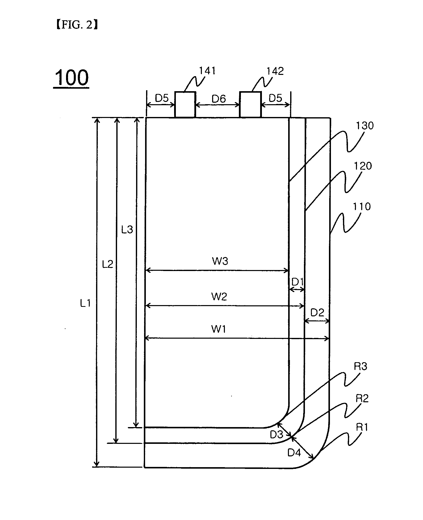
[0069]FIG. 2 is a plan view typically showing an electrode assembly according to an embodiment of the present invention and FIG. 3 is a plane view typically showing an electrode sheet notched to manufacture the electrode assembly according to the present invention.

[0070]Referring to FIGS. 2 and 3, an electrode assembly 100 includes a first unit cell 110, a second unit cell 120, a third unit cell 130, and electrode tabs 141 and 142. The second unit cell 120 is stacked on the upper end of the first unit cell 110. The third unit cell 130 is stacked on the upper end of the second unit cell 120. The second unit cell 120 has a smaller planar size than the first unit cell 110. The third unit cell 130 has a smaller planar size than the second unit c...


PUM

PropertyMeasurementUnit
lengthaaaaaaaaaa
lengthaaaaaaaaaa
lengthaaaaaaaaaa

Abstract

Disclosed herein is an electrode assembly including two or more unit cells, each of which includes a cathode, an anode, and a separator disposed between the cathode and the anode, electrode tabs protruding from the respective electrodes, wherein the unit cells are stacked in a height direction on the basis of a plane, at least two of the unit cells having different planer sizes, and one or more corners of each of the unit cells, which do not tangent to one side of each of the unit cells at which the electrode tabs are formed, are round.

Description

TECHNICAL FIELD[0001]The present invention relates to an electrode assembly including two or more unit cells, each of which includes a cathode, an anode, and a separator disposed between the cathode and the anode, electrode tabs protruding from the respective electrodes, wherein the unit cells are stacked in a height direction on the basis of a plane, at least two of the unit cells having different planer sizes, and one or more corners of each of the unit cells, which do not tangent to one side of each of the unit cells at which the electrode tabs are formed, are round.BACKGROUND ART[0002]As mobile devices have been increasingly developed, and the demand for such mobile devices has increased, the demand for secondary batteries has also sharply increased. Among such secondary batteries is a lithium secondary battery exhibiting high energy density and operating voltage and excellent charge retention and service-life characteristics, which has been widely used as an energy source for v...

Claims


Application Information

Patent Timeline
Patent Type & Authority Applications(United States)
IPC IPC(8): H01M4/02H01M50/105H01M50/55H01M50/557H01M50/566
CPCH01M4/02H01M4/13H01M10/052H01M10/0585H01M10/0587Y02E60/10H01M50/557H01M50/103Y02P70/50H01M50/105H01M50/55H01M50/566
Inventor KWON, SUNGJINKIM, KI WOONGKIM, DONG-MYUNG
Owner LG ENERGY SOLUTION LTD
Learn More