
Power source control apparatus for vehicle

a technology for controlling apparatus and power source, which is applied in the direction of road transportation emission reduction, transportation and packaging, and propulsion using engine-driven generators, etc. it can solve the problems of limited battery charge, increased burden of auxiliary power source, and insufficient power supply to electric devices, so as to prevent any improper deterioration

Active Publication Date: 2016-02-09
MAZDA MOTOR CORP
View PDF8 Cites 7 Cited by
  • Summary
  • Abstract
  • Description
  • Claims
  • Application Information

AI Technical Summary

Benefits of technology

The present invention provides a power-source control apparatus for a vehicle that can manage high electric loads and prevent excessive battery discharge when using a capacitor as a regenerative power storage means.

Problems solved by technology

In the system described above, however, since the battery of the main power source may deteriorate through its frequent charge / discharge, it may be necessary that the charge of the battery is restricted and a burden of the auxiliary power source is increased.
Further, there is a problem in that if the amount of power storage of the auxiliary power source is small, a sufficient amount of power may not be supplied to the electric devices.
However, in a case in which the above-described capacitor having the high capacity is used, even when the load of the electric devises is high and the output of the capacitor is sufficient, if a capacity (output current) of the DC / DC convertor provided between the electric devices and the capacitor is short, the sufficient power may not be supplied to the electric devices.
This may cause problems of a cost increase as well as a large size.
However, if a remaining capacity of the battery becomes too low, that is—the battery is excessively discharged, there is a concern that problems of the battery being dead or the battery's deterioration may occur.

Method used


Image

  • Power source control apparatus for vehicle
  • Power source control apparatus for vehicle
  • Power source control apparatus for vehicle

Examples


Embodiment Construction

[0030]Hereafter, a preferred embodiment of the present invention will be described.

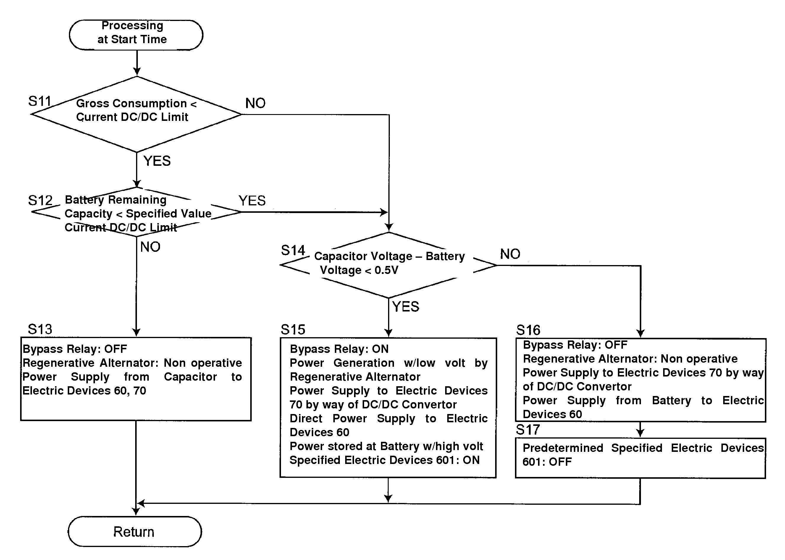
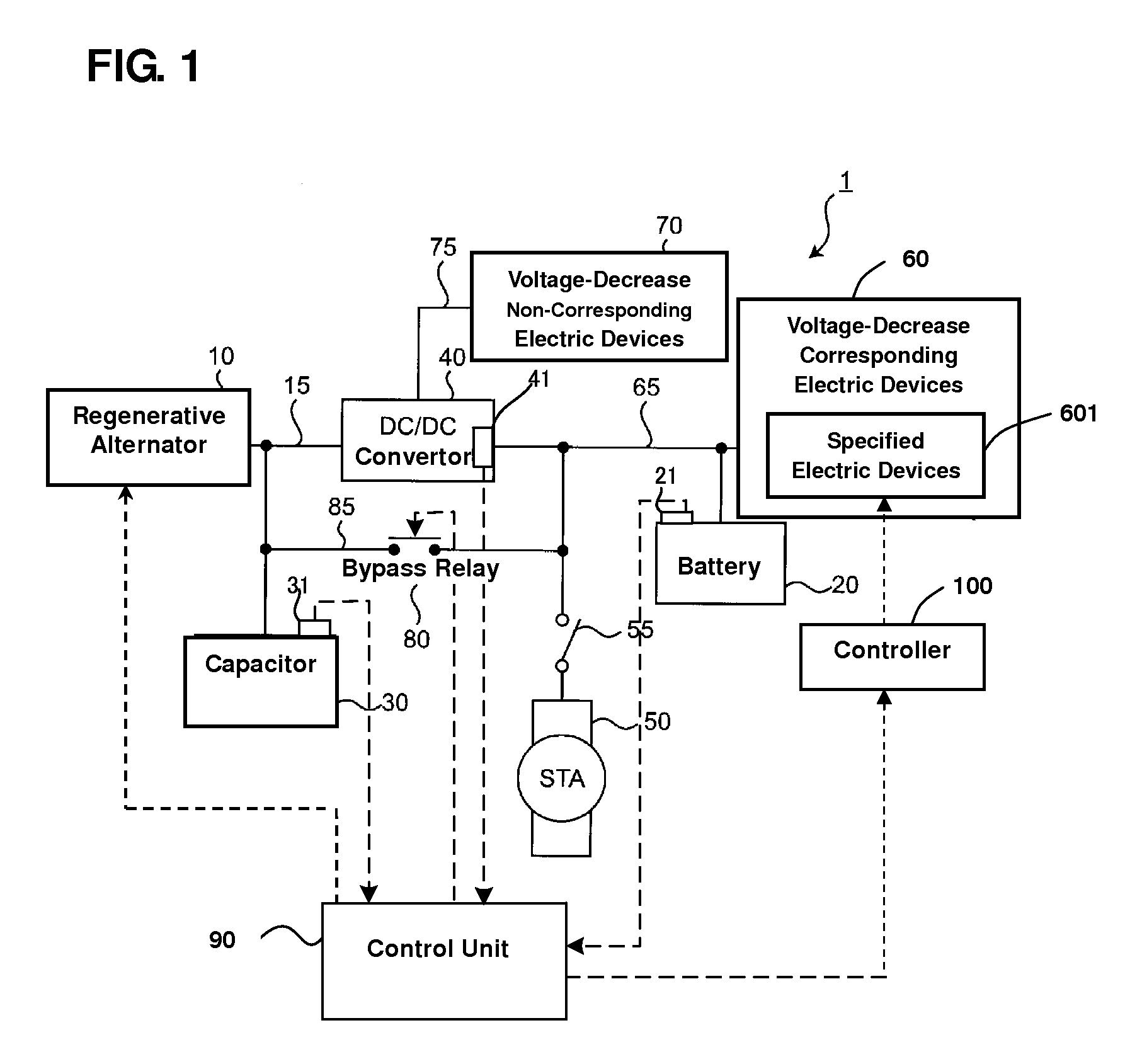
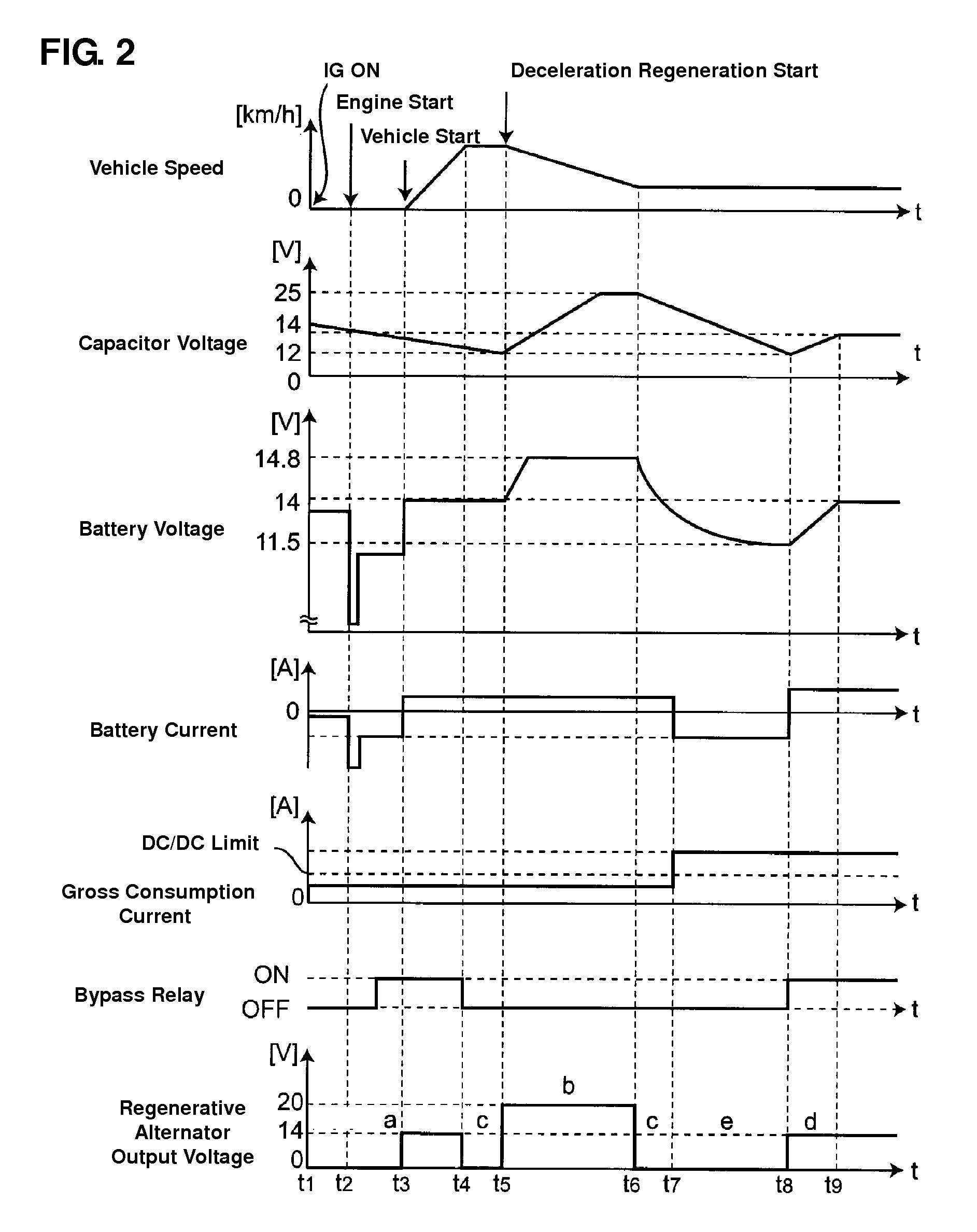
[0031]FIG. 1 shows a deceleration-regeneration system 1, to which a power-source control apparatus for a vehicle of the present embodiment is applied. The deceleration-regeneration system 1 comprises a regenerative alternator 10 which is capable of a deceleration-regeneration power generation conducted at the time of deceleration of the vehicle and a normal power generation conducted by driving an engine (not illustrated), a battery 20, a capacitor 30 which is capable of storing the power generated by the regenerative alternator 10, a DC / DC convertor 40 which controls power supply to plural voltage-decrease corresponding electric devices (plural electric devices capable of corresponding to voltage decrease) 60 (including specified electric devices 601 as a specified electric load) and voltage-decrease non-corresponding electric devices (electric devices incapable of corresponding to voltage decrease) ...


PUM


Abstract

A battery, a regenerative generator, a capacitor capable of storing power generated by the regenerative generator, and a DC / DC convertor capable of allowing an output current to flow up to a specified permissible limit value are provided. The capacitor is connected to a first circuit portion connecting the regenerative generator and the DC / DC convertor. The battery is connected to a second circuit portion connecting the DC / DC convertor and electric loads. Thereby, power from the capacitor is supplied to electric loads by way of the DC / DC convertor until the output current of the DC / DC convertor reaches the specified permissible limit value, whereas power from the battery is supplied to the electric loads after the output current of the DC / DC convertor has reached the specified permissible limit value. A specified electric load is turned OFF when the power from the battery is supplied.

Description

BACKGROUND OF THE INVENTION[0001]The present invention relates to a power-source control apparatus for a vehicle which is equipped with a regenerative generator conducting deceleration regeneration, and in particular to a power-source control apparatus for a vehicle which can provide a stable power supply even when a load of electric devices is high.[0002]Recent years, a vehicle which has a function of regenerating deceleration energy at the time of deceleration of the vehicle and utilizing the regenerated energy as a power supply to electric devices, in addition to improving combustion of an engine, reducing vehicle weight, and so on, in order to improve the fuel efficiency (gas mileage) has been put to practical use.[0003]US Patent Application Publication No. 2006 / 0097577 A1, for example, discloses a vehicle power supply system which comprises a main power source for power supply to a starter and general electric devices, which is comprised of a normal battery, an auxiliary power ...

Claims


Application Information

Patent Timeline
Patent Type & Authority Patents(United States)
IPC IPC(8): H02J7/00B60R16/03B60L50/10B60R16/033
CPCB60R16/033B60R16/0307Y02T10/92
Inventor YOSHIDA, KATSUMASAMORIMOTO, SHOSUKEKOTANI, KAZUYAIMAMURA, TOMOYUKI
Owner MAZDA MOTOR CORP
Learn More