Card edge connector with an improved metal hook

a metal hook and card edge technology, applied in the direction of coupling device connection, coupling parts engagement/disengagement, electrical equipment, etc., can solve the problem of terribly affected signal transmission between the daughter board and the mother board

Active Publication Date: 2011-02-10
HON HAI PRECISION IND CO LTD
View PDF12 Cites 6 Cited by
  • Summary
  • Abstract
  • Description
  • Claims
  • Application Information

AI Technical Summary

Benefits of technology

[0007]According to another aspect of the present invention, a card edge connector for being mounted to a mother board and receiving a daughter board, comprises an insulative housing having a pair of opposed side walls, an end wall connected to the side walls, a retainer protruding outwardly from the end wall in a lengthwise direction of the housing, a central slot formed between the side walls and the end wall for receiving the daughter board; a plurality of terminals received in the housing and extending into the central slot for mating with the daughter board; and a metal hook retained on the end wall along an upper-to-lower direction of the housing, and having a soldering tail extending beyond the housing f

Problems solved by technology

Signal transmission between the daughter boa

Method used


Image

  • Card edge connector with an improved metal hook
  • Card edge connector with an improved metal hook
  • Card edge connector with an improved metal hook

Examples


first embodiment

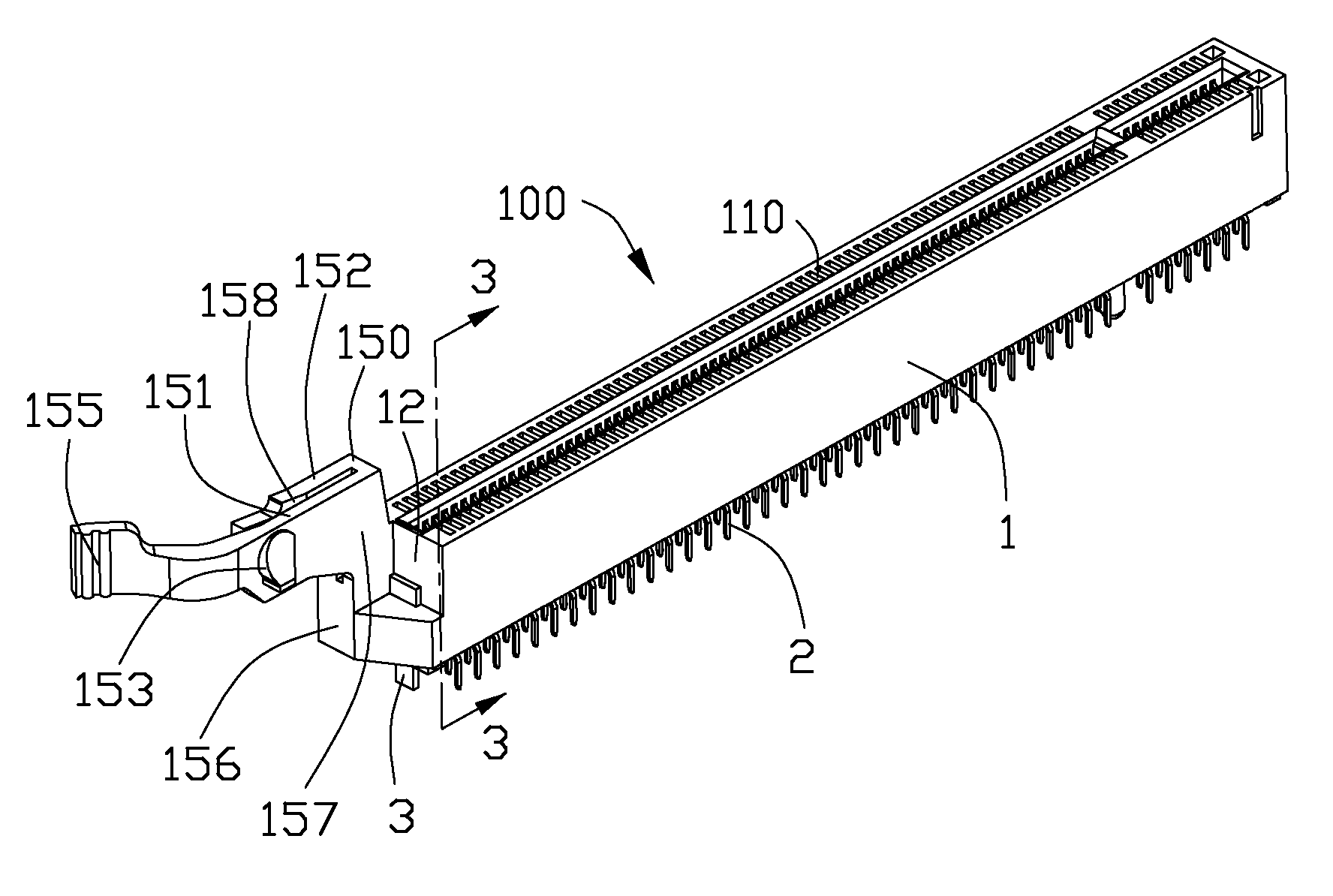
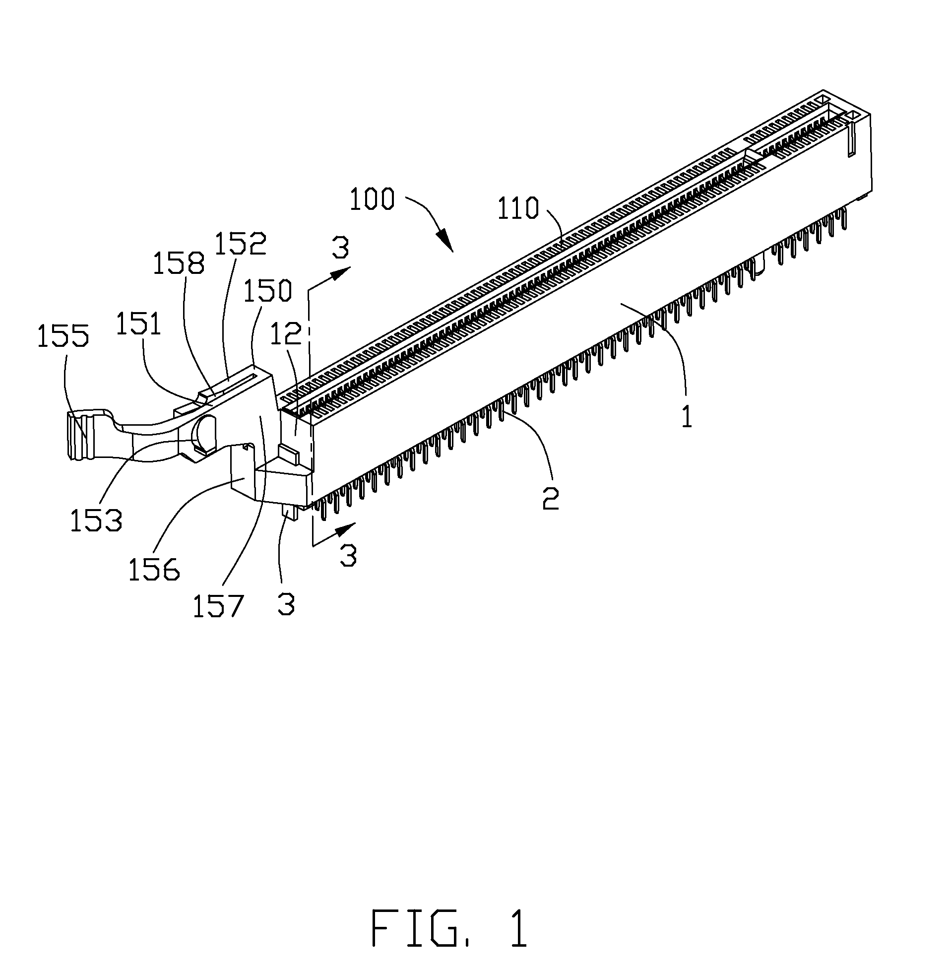
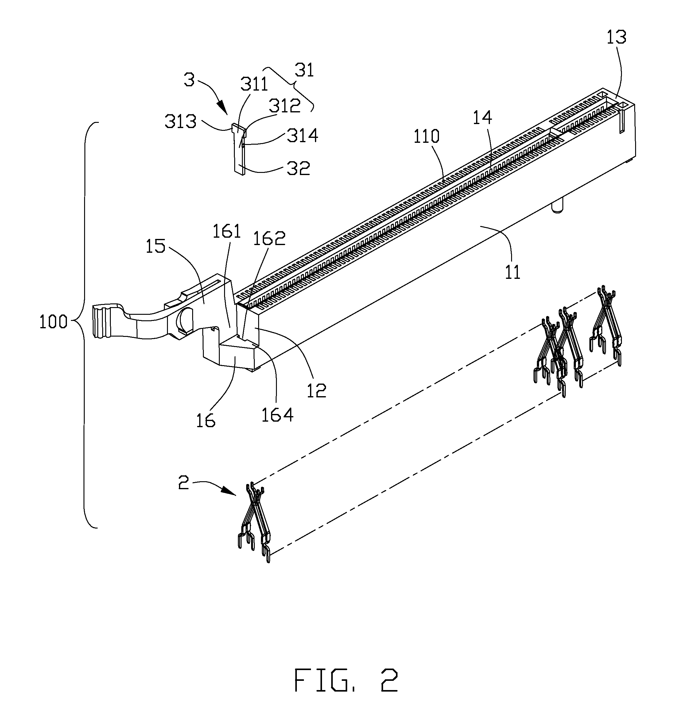
[0025]Referring to FIGS. 1-3, a card edge connector 100 for receiving an daughter board (not shown) according to the present invention is disclosed. The card edge connector 100 includes an insulative housing 1, a plurality of terminals 2 retained in the housing 1 and a metal hook 3 assembled to the housing 1 along an upper-to-lower direction of the housing 1.

[0026]The housing 1 includes a pair of elongated side walls 11, a first end wall 12, and a second end wall 13 opposited to the first end wall 12. A central slot 14 is formed between the side walls 11 and the end walls 12, 13 for receiving the daughter board. Two rows of passageways 110 are formed in the side walls 11 for retaining the terminals 2. The terminals 2 each extends into the central slot 14 for mating with the daughter board. The housing 1 further includes a retainer 15 and a level reinforcement wall 16 both of which protruding outwardly from the first end wall 12 in a lengthwise direction of the housing 1.

[0027]The re...

second embodiment

[0030]Referring to FIGS. 4-6, a card edge connector 200 according to the present invention is disclosed. The card edge connector 200 also comprises an insulative housing 4, a plurality of terminals 5 received in the housing 4, and a metal hook 6 retained at one side of the housing 4. The hook 6 is similar to a metal screw and includes a fitting portion 61 and a soldering tail 62 for being soldered onto a hole of the mother board for the card edge connector 200 mounted on the mother board reliably. The fitting portion 61 includes an upper column fitting portion 611 and a lower column fitting portion 612 extending downwardly from the upper fitting portion 611. The lower fitting portion 612 is retained in a through hole 462 of a reinforcement wall 46 of the housing 4. The upper fitting portion 611 defines a shoulder 613 protruding laterally beyond the lower fitting portion 612. The shoulder 613 presents as a semi-cylinder shape and presses downwardly against an upper level supporting p...

third embodiment

[0031]Referring to FIGS. 7-10, a card edge connector 300 according to the present invention is disclosed. The card edge connector 300 also comprises an insulative housing 7, a plurality of terminals 8 retained in the housing 7, and a metal hook 9 retained on an end wall 72 of the housing 7. The hook 9 is formed from a metal plate, and includes an U sharp fitting portion 91, and a soldering tail 92 for being mounted on a mother board for the card edge connector 300 being mounted on the mother board reliably. The fitting portion 91 includes a pair of flexible arms 911 extending upwardly and a gap 912 formed therebetween. The flexible arms 911 can be deflected toward each other. The end wall 72 defines a through hole 721. The flexible arms 911 are retained in the through hole 721 and pressing outwardly against inner walls of the through hole 721 respectively. A lower portion of each of the flexible arms 911 defines a projection 915 locking with a block 725 on the inner wall of the thro...


PUM


Abstract

A card edge connector (100) includes an insulative housing (1) having a pair of opposed side walls (11), a end wall (12) connected to the side walls (11), a retainer (15) and a reinforcement wall (16) both of which protruding outwardly from the end wall (12) in a lengthwise direction of the housing (1); a plurality of terminals (2) received in the housing (1); and a metal hook (3) retained on the reinforcement wall (16) along an upper-to-lower direction of the housing (1), and having a soldering tail (32) extending beyond the housing (1) for being mounted to a mother board. The retainer (15) is connected to the reinforcement wall (16) and defines a latch projection (153) extending from an inner surface for latching a daughter board.

Description

BACKGROUND OF THE INVENTION[0001]1. Field of the Invention[0002]The present invention relates to card edge connectors, more particularly to a card edge connector with an improved metal hook for being mounted to a mother board.[0003]2. Description of Related Art[0004]Card edge connectors are employed widely in computers to receive a daughter board, a memory card, graphic card, network interface card et al. The card edge connector usually has an insulative housing, a plurality of contacts retained in the housing for electrically connecting a corresponding daughter board, and a board lock retained on the housing for fixing the card edge connector on a mother board. The housing defines a retainer for retaining the daughter board on the card edge connector. The board lock includes a fitting portion, and a mounting tail extending downwardly beyond the housing from the fixing portion. A bottom portion of the housing defines a retaining slot to retain the fixing portion. The fixing portion ...

Claims


Application Information

Patent Timeline
IPC IPC(8): H01R13/62
CPCH01R12/721H01R12/7011
Inventor YAO, ZE-LINLI, ZHUANG-XINGFU, XIAO-ZHI
Owner HON HAI PRECISION IND CO LTD
Why Eureka
Try Eureka