Connector mounting structure

Active Publication Date: 2011-02-10
SUMITOMO WIRING SYST LTD
View PDF6 Cites 0 Cited by
  • Summary
  • Abstract
  • Description
  • Claims
  • Application Information

AI Technical Summary

Benefits of technology

The engagement of the projections with the restricting holes prevents the connector from inclining with respect to a proper mounting direction. Further, the contact of the auxiliary projections on the outer surface of each inner wall of the connector with the corresponding locks of the support from below prevents detachment of the connector from the support.
The above-described construction permits movement of a connector in a direction intersecting a proper mounting direction and prevents detachment of the connector from a bracket while restricting the inclination of the connector with respect to the proper mounting direction.

Problems solved by technology

However, the connector easily inclines with respect to a proper mounting direction before mounting the connector and the axial center of the connector is not easily oriented toward the mount hole.
Loose movements of the connector with respect to the bracket can be restricted, but a mount position cannot be adjusted finely when attaching another part to the bracket after the connector has been mounted.

Method used


Image

  • Connector mounting structure
  • Connector mounting structure
  • Connector mounting structure

Examples


Embodiment Construction

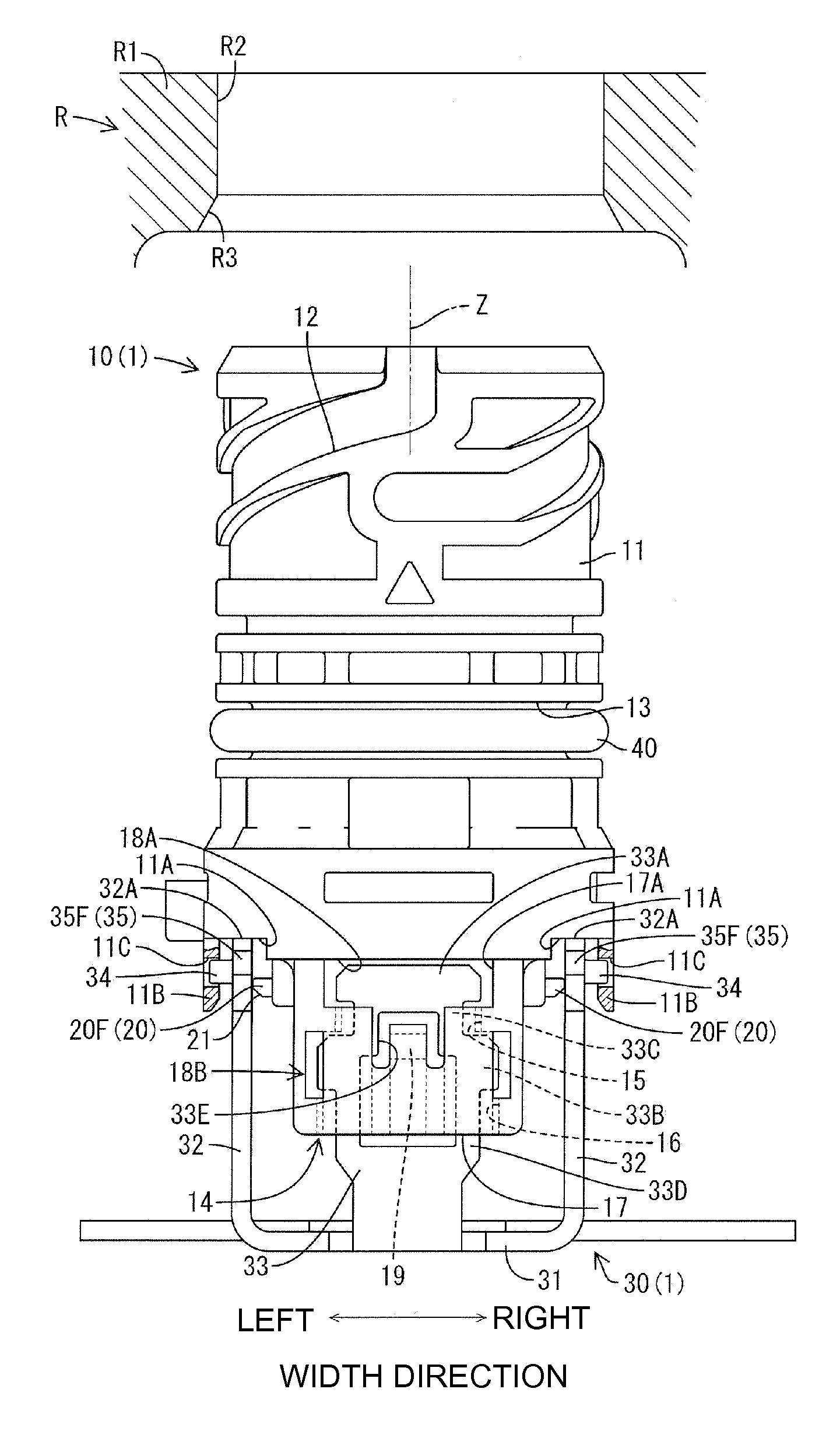
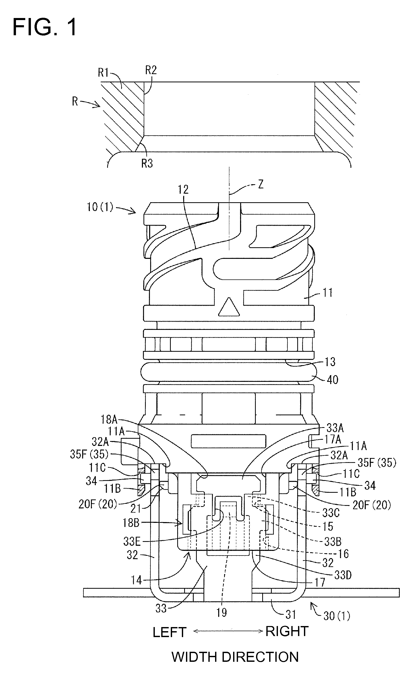
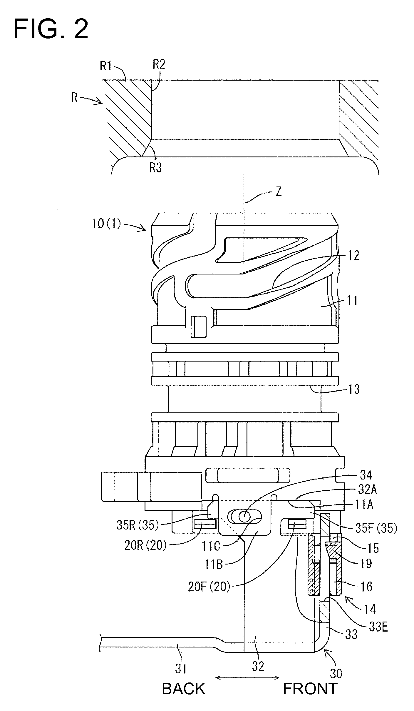
An electrical component in accordance with the invention is identified by the numeral 1 in FIGS. 1 to 8. The electrical component 1 is arranged on an automatic transmission case of an automotive vehicle (not shown) and can be connected electrically to an external circuit via a case R. In the following description, the width direction corresponds to lateral directions of FIG. 1 and forward and backward directions correspond to lateral directions of FIG. 2. The right side of FIG. 2 is referred to as the front and the vertical direction of FIGS. 1 and 2 is referred to as the vertical direction.

The case R includes a plate R1 made e.g. of synthetic resin. The plate R1 has an external-circuit connecting portion (not shown) to be connected with the external circuit and an electrical-component connecting portion (not shown) to be connected with the electrical component 1. The electrical-component connecting portion is provided in a mount hole R2 in the lower surface of the plate R1, as show...


PUM


Abstract

A bracket (30) includes a mounting piece (33) loosely movably supporting a connector (10) in a direction parallel with a plane intersecting a Z axis that is parallel to a longitudinal axis of the connector (10). The bracket (30) has restricting pieces (32) at opposite sides of the mounting piece (33). Locks (35) are formed at opposite sides of each restricting piece (32) and a projection (34) is formed on the outer surface of each restricting piece (32). The connector (10) includes a side wall (26A) at an inner side of each restricting piece (32), a deflecting piece (11B) for sandwiching the restricting piece (32) together with the side wall (26A). Auxiliary projections (20) are formed on the outer surface of each side wall (26A) and can contact the locks (35) from below. A restricting hole (11C) is formed in each deflecting piece (11B) for engaging the projection (34).

Description

BACKGROUND OF THE INVENTION1. Field of the InventionThe invention relates to a connector mounting structure.2. Description of the Related ArtU.S. Pat. No. 7,189,101 discloses an electrical component with a connector that is loosely movably supported in a bracket. The electrical component may be used, for example, in an automatic transmission of an automotive vehicle. The connector is mounted in a mount hole of a mating member by assembling the electrical component with the mating member. The loose movable support of the connector on the bracket prevents exertion of unnecessary force on the connector as the connector is being mounted into the mount hole. However, the connector easily inclines with respect to a proper mounting direction before mounting the connector and the axial center of the connector is not easily oriented toward the mount hole. Loose movements of the connector with respect to the bracket can be restricted, but a mount position cannot be adjusted finely when attach...

Claims


Application Information

Patent Timeline
IPC IPC(8): H01R13/629
CPCH01R13/6315
Inventor UCHIDA, MASASHITSUCHIDA, YUSUKE
Owner SUMITOMO WIRING SYST LTD
Why Eureka
Try Eureka