Connector

Active Publication Date: 2019-02-07
YAZAKI CORP
View PDF9 Cites 0 Cited by
  • Summary
  • Abstract
  • Description
  • Claims
  • Application Information

AI Technical Summary

Benefits of technology

The invention provides a connector that can prevent terminal metal fittings from tilting or displacing in the housing chamber, even if there is an opening region between neighboring chambers. This is achieved by a support wall that supports the tip portion of the terminal metal fitting, preventing it from tilting or displacing. This design prevents improper electrical connection and ensures reliable performance of the connector.

Problems solved by technology

If the terminal metal fitting may be inclined too much, trouble may occur that in fitting the connector with a counterpart connector the terminal metal fitting cannot come into contact with a counterpart terminal properly and proper electrical connection cannot be established between them.

Method used


Image

  • Connector
  • Connector
  • Connector

Examples


embodiment

[0026]A connector 1 according to an embodiment of the present invention will be hereinafter described with reference to the drawings.

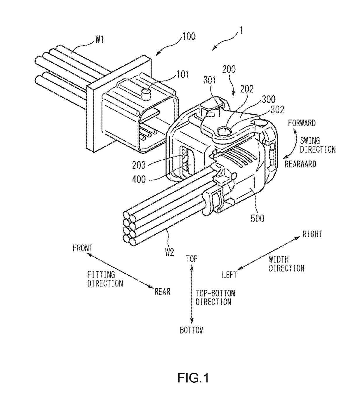
[0027]As shown in FIG. 1, the connector 1 according to the embodiment of the invention is equipped with a male housing 100, a female housing 200 which is fitted with the male housing 100 so as to house it (the male housing 100 is inserted in the female housing 200), a lever 300 which is attached to the female housing 200 swingably, a spacer 400 which is disposed in the female housing 200, and a wire cover 500 which is attached to the female housing 200.

[0028]The “fitting direction,”“width direction,”“top-bottom direction,”“front side,”“rear side,”“left side,”“right side,”“top,”“bottom,” and “swing direction” of the lever 300. The fitting direction, the width direction, and the top-bottom direction are perpendicular to each other. FIG. 1 shows a state that the lever 300 is located at a tentative lock position (fitting start position). The lever 300 is m...


PUM


Abstract

A connector (1) includes a housing (200), a terminal metal fitting (T2) inserted into a housing chamber (201) forwardly in a housing direction, and a spacer (400) locking the terminal metal fitting. The terminal metal fitting has a plate-like lock piece (T2a) extending in the housing direction. The terminal metal fitting is locked by contacting a rear edge (T2aa) of its lock piece with the spacer. The housing has an opening region between two adjacent terminal housing chambers and a support wall (205) extending from a peripheral end portion of the opening region backwardly in the housing direction. The support wall supports a tip portion (T2b) of the terminal metal fitting to eliminate movement of the tip portion through the opening region, even when the terminal metal fitting moves backwardly in the housing direction while allowing the rear edge of its lock piece digging into the spacer.

Description

CROSS-REFERENCES TO RELATED APPLICATION(S)[0001]This application is based on and claims priority from Japanese Patent Application No. 2017-151686 filed on Aug. 4, 2017, and the entire contents of which are incorporated herein by reference.BACKGROUNDField of the Invention[0002]The present invention relates to a connector that is equipped with a housing having plural terminal housing chambers, terminal metal fittings that are housed in the respective terminal housing chambers, and a spacer that locks the terminal metal fittings so as to restrict movement of the terminal metal fittings toward the rear side in their housing direction.Description of Related Art[0003]Connectors using a spacer that locks terminal metal fittings so that they are kept at prescribed positions in terminal housing chambers, respectively, are known.[0004]For example, in one conventional connector (hereinafter referred to as “conventional connector”), from the viewpoint of, for example, its size reduction, an ope...

Claims


Application Information

Patent Timeline
IPC IPC(8): H01R13/436H01R13/10
CPCH01R13/4361H01R13/10H01R13/62938H01R13/436H01R13/4223H01R13/62933
Inventor SHIMIZU, TOMOHIKO
Owner YAZAKI CORP
Why Eureka
Try Eureka