Method, device and apparatus for dispensing polyurethane mixtures

Active Publication Date: 2017-02-09
CANNON S P A VIA C COLOMBO
View PDF0 Cites 3 Cited by
  • Summary
  • Abstract
  • Description
  • Claims
  • Application Information

AI Technical Summary

Benefits of technology

[0020]It is another object to enabling the foaming of objects, especially panels, having a length that is much greater, especially double, than the length currently achievable with conventional foaming systems, while maintaining the same number of dispensers currently applied i

Problems solved by technology

For this reason, the two parts composing the bar distributor are mutually coupled and tightened by means of a number of quite robust screws, whereby unfortunately said screws make the disassembly operations for periodic cleaning purposes very difficult, as they add the need to perfectly clean both the meatus and the distribution duct, so as to restore the critical surfaces thereof, whereby the carrying out of these operations turns out to take a very long time, leading to expensive operations for replacing and cleaning the bars in the production facilities, these operations resulting in a significant increase in costs.
A serious drawback of the bar distributor described above is the dishomogeneity of the reacting resin flow along the distribution channel supplying the meatus: in the middle section, closer to the mixing head, the flow along the duct is meant to feed not only the meatus in front thereof, but also the remaining meatus extending towards the side ends.
All this rapidly leads to having areas of the meatus that are completely occluded and areas that are never occluded, this resulting in an inadmissible dishomogeneity in the distribution of the mixture along the discharge meatus.
In other words, when there is an attempt to increase the speed along the distribution channel so as to keep it clean as a result of the washing effect, such an increase in speed disturbs the feeding of the meatus by generating a higher depression where the flowing speed is higher.
All this has a negative impact on both the homogeneity and the quality of the foamed product.
Yet, this distribution device, too, has man

Method used


Image

  • Method, device and apparatus for dispensing polyurethane mixtures
  • Method, device and apparatus for dispensing polyurethane mixtures
  • Method, device and apparatus for dispensing polyurethane mixtures

Examples


Embodiment Construction

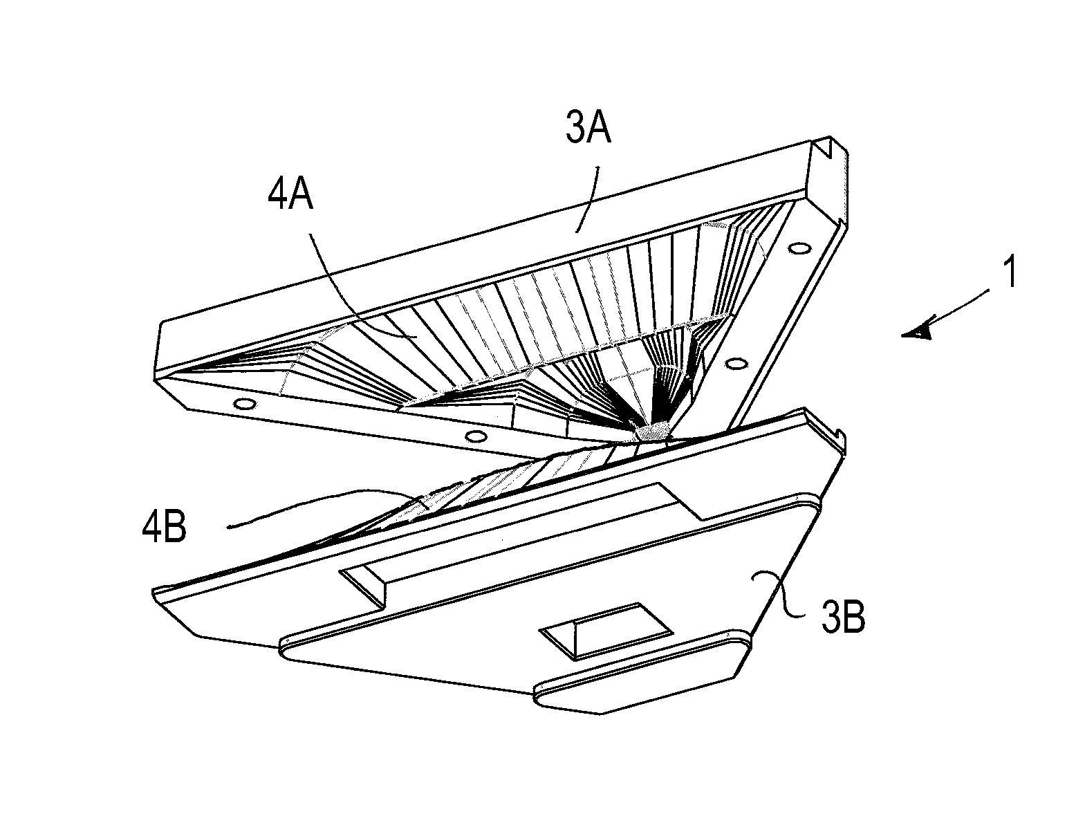
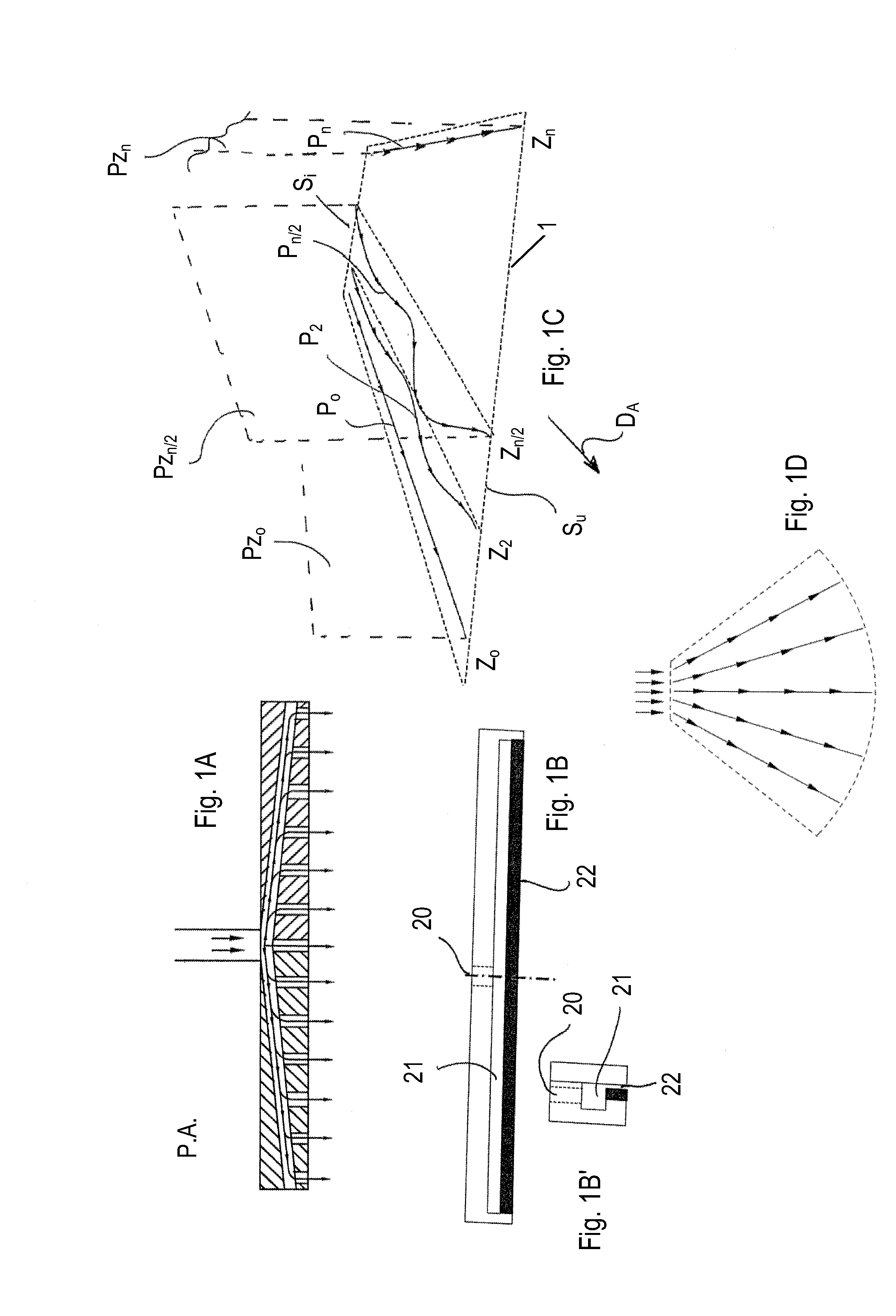
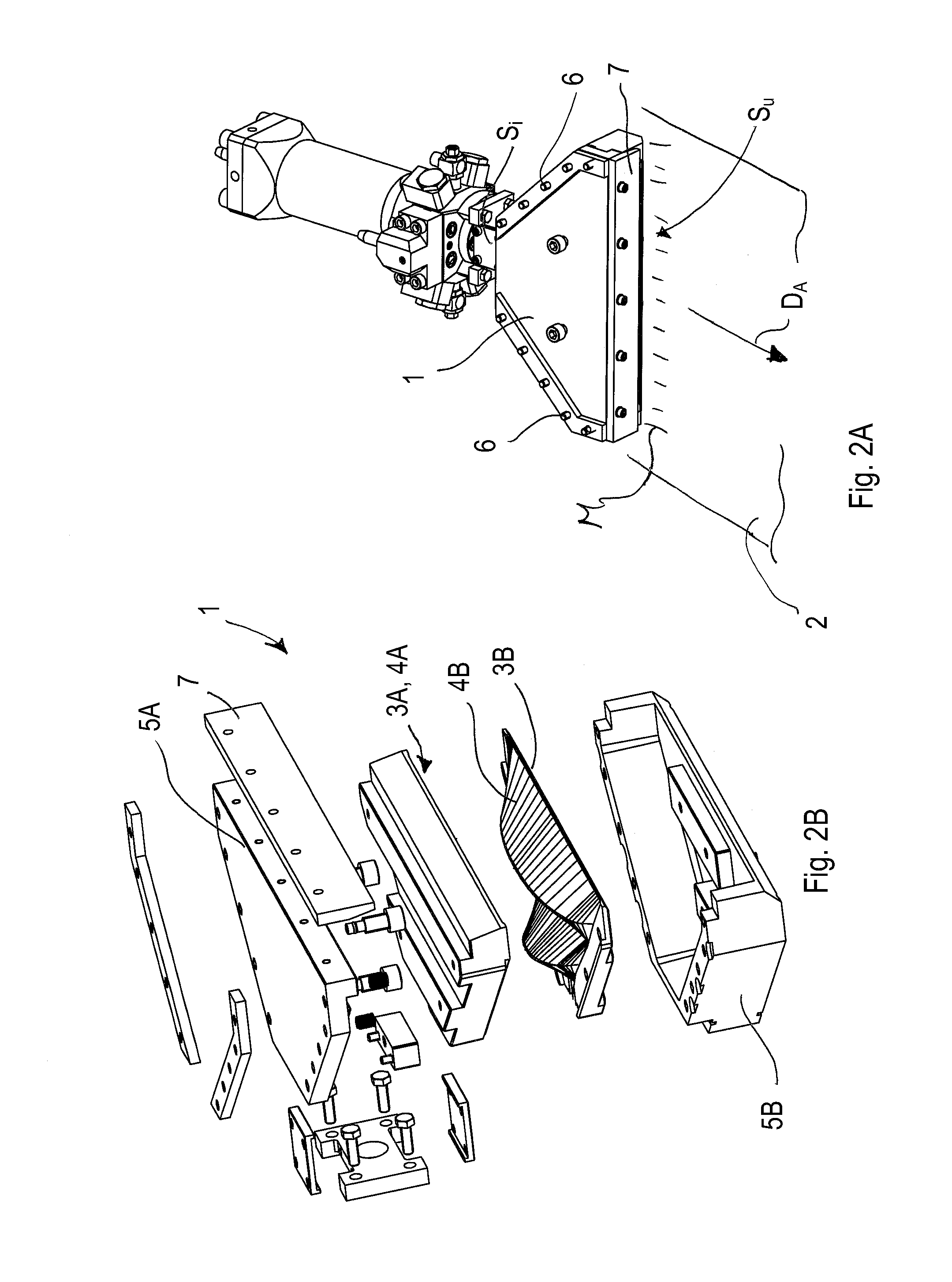
[0079]With reference to the accompanying drawings, there is described a device 1 according to the invention for dispensing and distributing a reactive mixture, and an apparatus 100 provided with a plurality of said devices 1, for continuously foaming a panel.

[0080]The apparatus 100 comprises supporting means 101, such as a supporting bench or table, for a substrate 2 to be foamed, e.g., a paper web or any other desired web material that is run along an advancement direction DA. The dispensing and distributing devices 1 are aligned side by side, transversely to the advancement direction DA. A plurality of single dispensing devices 1, for example 3 or 4 devices arranged side by side, is also possible, each of them being fed by a respective mixing head. In an alternative arrangement, the dispensing devices 1 are coupled in pairs, each pair being fed by a respective common mixing head.

[0081]A dispensing station E is provided close to the supporting bench or table 101, to apply a thin, u...


PUM

PropertyMeasurementUnit
Lengthaaaaaaaaaa
Timeaaaaaaaaaa
Angleaaaaaaaaaa

Abstract

A method is disclosed for dispensing a polyurethane mixture onto a substrate by generating a liquid mixture from reactive component resins; introducing the mixture in an inlet section of a dispensing device so as to advance it towards a planar-shaped outlet slit section, transversely to the advancement direction of the substrate; distributing the mixture along a gap chamber having a cross section diverging towards the outlet slit section; and dispensing the mixture through the outlet slit section, so as to deposit a thin, uniform film onto the substrate. Fractions of the mixture travel equal distances from the inlet section to the outlet slit section, in equal times, maintaining equal average speeds along each section having zones placed all at the same path distance either from the inlet section or from the outlet slit section.

Description

BACKGROUND OF THE INVENTION[0001]The present invention relates to a method, a device and an apparatus for dispensing a mixture of chemical reactive components containing possible expanding agents, for foaming panels or, in general, substantially bi-dimensional objects, i.e., objects having two dimensions prevailing over a third dimension. The invention also relates to an apparatus including one or more pairs of dispensing devices, and to the related system for treating the dispensed flows.STATE OF THE ART[0002]There are currently known devices for dispensing polyurethane mixtures that receive the mixture just generated from a mixing head and distribute it onto an underlying substrate, e.g., a paper web, that moves onto a conveyor belt. The mixing head provides for the combination of two or more chemically reactive component resins in the liquid state, with the possible addition of additives and / or expanding agents dissolved in solution at ambient pressure or under pressure, and of e...

Claims


Application Information

Patent Timeline
IPC IPC(8): B05D7/00C09D175/04B29C48/08B29C48/305
CPCC09D175/04B05D7/50B05C5/0254B05C5/0258B29C39/16B29C43/22B29C44/306B29C44/461B29K2075/00B29K2105/04B29L2031/776B29C48/08B29C48/2566B29C48/305
Inventor VOLPATO, MARCOCORTI, MAURIZIO
Owner CANNON S P A VIA C COLOMBO
Why Eureka
Try Eureka