Haemostatic valve assembly

a technology of haemostatic valve and assembly, which is applied in the direction of valves, intravenous devices, medical devices, etc., can solve the problems of valves failing to provide seals, etc., and achieve the smoothest movement and sliding, the effect of increasing the efficiency and sealing characteristics of the valve, and extending the sealing function

Active Publication Date: 2013-11-19
COOK MEDICAL TECH LLC
View PDF18 Cites 0 Cited by
  • Summary
  • Abstract
  • Description
  • Claims
  • Application Information

AI Technical Summary

Benefits of technology

[0011]Preferably, the flexible valve element extends across the entirety of a space between the openings. The structure will work with a valve element which extends across only a part of the distance between the ends of the housing. For instance, a part of this space could be taken up with a wall or support structure extending from the housing end towards the middle of the housing and which provides no valving function but which simply supports a shorter valve element. It is preferred, however, that the flexible valve element extends across the entirety of the distance between the two ends of the housing as this would provide a greater length of sealing function, which can substantially increase the efficiency and sealing characteristics of the valve compared to a valve which seals over only a shorter distance.
[0012]In the preferred embodiment the pellets are substantially spherical. This shape ensures smoothest movement and sliding of the pellets with respect to one another. Other shaped pellets are, however, not excluded. The pellets could, for example, be oval, rod-shaped, irregularly shaped or of any other shape which allows them to move and slide with respect to one another.
[0014]It is preferred that the pellets are formed of a compressible or compliant material, advantageously an elastomeric material such as at least one of rubber, a rubber-like material, silicon, a foam. The use of compliant pellets enables these to deform, typically to compress, when they are subjected to a compression force, for instance when an element is introduced into the valve. This compliance ensures that the pellets impart on the valve element and in particular on the lumen of the valve element a constant sealing force. It is not, however, necessary for the pellets to be made of a compressible material. For instance, the housing could be made at least partially of a compliant or elastomeric material to allow for movement of the pellets and to provide for the necessary restoring or biasing force to the valve assembly. In other embodiments, the valve element can provide the necessary compliancy of the structure to allow movement of rigid pellets as an element is introduced into the valve assembly.

Problems solved by technology

This, however, involves at least one additional step in the medical procedure and can also lead to the valve failing to provide a seal when in the open configuration, therefore requiring additional valving to avoid unnecessary bodily fluid loss during operation of the valve.

Method used


Image

  • Haemostatic valve assembly
  • Haemostatic valve assembly
  • Haemostatic valve assembly

Examples


Embodiment Construction

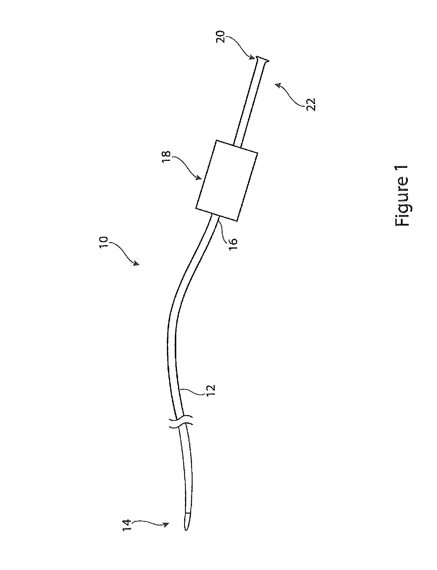
[0023]Referring to FIG. 1 there is shown an example of introducer assembly 10, having a general form which is conventional in the art but which is provided with a haemostatic assembly as taught herein. The introducer assembly 10 may be used for the endoluminal implantation in a patient of medical devices such as stents, stent grafts, vena cava filters, occluders and other such devices. The introducer 10 may also be used for the deployment of any other medical treatment and / or diagnostic tools.

[0024]The introducer assembly 10 includes, as it typical, a sheath 12 designed to be fed through the vasculature of a patient. The sheath 12 has a distal end 14 which in use is positioned at the treatment site, and a proximal end 16 coupled to a haemostatic valve assembly 18 and which remains outside the patient during the procedure. A cannula or catheter element 20 extends from the haemostatic valve assembly 18 at a proximal end 22 of the introducer 10. The sheath 12, cannula 20 and haemostati...


PUM


Abstract

A haemostatic valve assembly (18) is provided with a housing (24) having first and second ends (26, 28) within each of which there is provided an aperture of opening (30, 32). A flexible valve element (34) is disposed within the housing (24) between the first and second openings (30, 32). A mass of separate pellets (40) is located within the chamber (38) formed between the housing (24) and the valve element (34). The pellets (40) apply pressure to the valve element (34) so as to close the lumen (36) thereof. The pellets (40) are preferably made of a compressible material and such that when an element is inserted through the openings (30, 32) and thus through the valve assembly (18) the pellets (40) compress to allow opening of the lumen (36). The biasing force of the pellets (40) against the valve (34) provide constant sealing pressure to the valve assembly (18) without the need for any intervention by the clinician. The valve assembly is therefore entirely automatic.

Description

FIELD OF THE INVENTION[0001]The present invention relates to a haemostatic valve assembly and to an introducer or deployment device incorporating such a valve assembly.BACKGROUND OF THE INVENTION[0002]There are well established techniques for carrying out endoluminal treatments and diagnoses on a patient. A diagnosis may, for example, involve injection of contrast material and saline solution. A treatment may, for example, involve insertion and deployment of implants or prostheses for carrying out surgical procedures. It may also or in the alternative involve insertion, use and removal of catheters or tools, such as angioplasty or moulding balloons. A treatment may also involve injection of contrast material, saline solution, administration of medicaments and so on. The treatments and diagnoses can be effected within a patient's vascular system, such as arteries or veins. They can also be carried out within other bodily tubes which carry pressurized fluids, examples being the bilary...

Claims


Application Information

Patent Timeline
Patent Type & Authority Patents(United States)
IPC IPC(8): A61M5/178
CPCA61M39/06A61M39/0606A61M39/0613A61M2039/0673
Inventor HANSEN, SEBASTIAN
Owner COOK MEDICAL TECH LLC
Why Eureka
Try Eureka