Light source apparatus

Active Publication Date: 2014-11-27
MITUTOYO CORP
View PDF5 Cites 0 Cited by
  • Summary
  • Abstract
  • Description
  • Claims
  • Application Information

AI Technical Summary

Benefits of technology

The present invention provides a light source apparatus that can accurately position the optical fiber with respect to the light source with minimal position adjustment effort. The orientation maintaining mechanism, axial line position adjustment mechanism, and planar position adjustment mechanism work together to ensure precise positioning of the optical fiber. The slip rings prevent inclination and reduce friction during position adjustment. The apparatus includes a holder and sleeve that can be fixated without additional tools, and the entire outer circumferential surface of the holder never contacts the inner circumferential surface of the sleeve, reducing friction. Overall, the light source apparatus allows for easy and accurate positioning of the optical fiber.

Problems solved by technology

S52-102746 uses an elastic body for the adjustment mechanism and cannot be said to be sufficient from a standpoint of ensuring stability and accuracy of an adjusted state.
However, the mechanism of Japanese Patent Laid-open Publication No. 2005-345984 has play in each component, as an adjustment margin, during adjustment and an adjustment operation to achieve a favorable positional relationship of the optical fiber and the LED is not necessarily easy.
S59-135415 as well, but, similar to Japanese Patent Laid-open Publication No. 2005-345984, the adjustment operation is not easy.
As in the above-noted Japanese Patent Laid-open Publication Nos. 2005-345984 and S59-135415, even when stability of the adjusted state is obtained by performing fixation after the adjustment operation, when there is play in the components during adjustment, highly accurate position adjustment becomes difficult.
S52-102746, 2005-345984, and S59-135415, the axis center position of the optical fiber can be matched for each axis direction along the light-receiving surface of the LED, but inclination or the like of the axis center of the optical fiber is difficult to adjust.
S59-135415, the inclination of the axis center direction of the optical fiber can be regulated by adjusting fixating screws in two locations mutually offset in the axis center direction of the optical fiber, but because there is nothing determining the position of the optical fiber during adjustment, highly accurate positioning adjustment is difficult.

Method used


Image

  • Light source apparatus
  • Light source apparatus
  • Light source apparatus

Examples


first embodiment

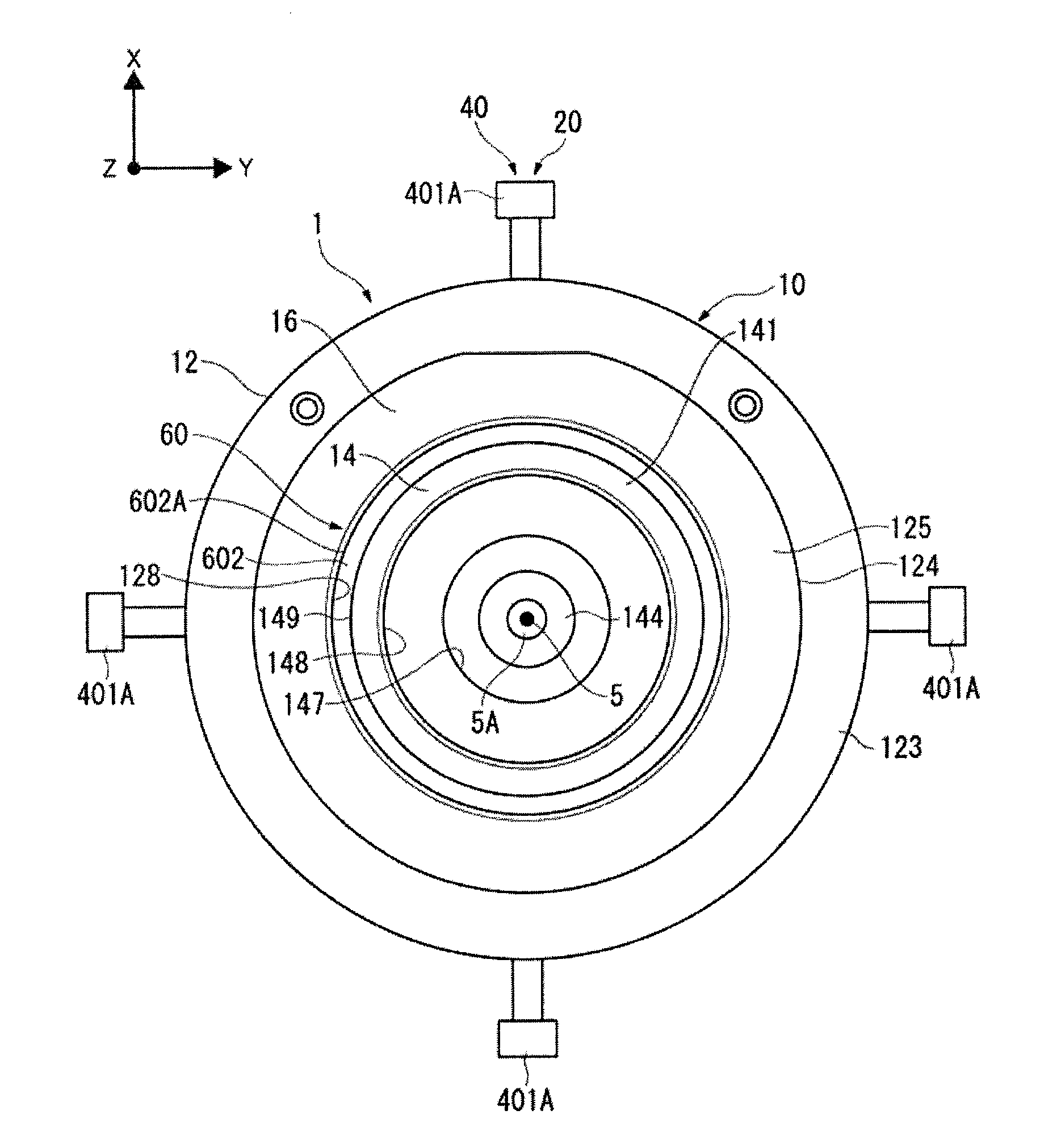
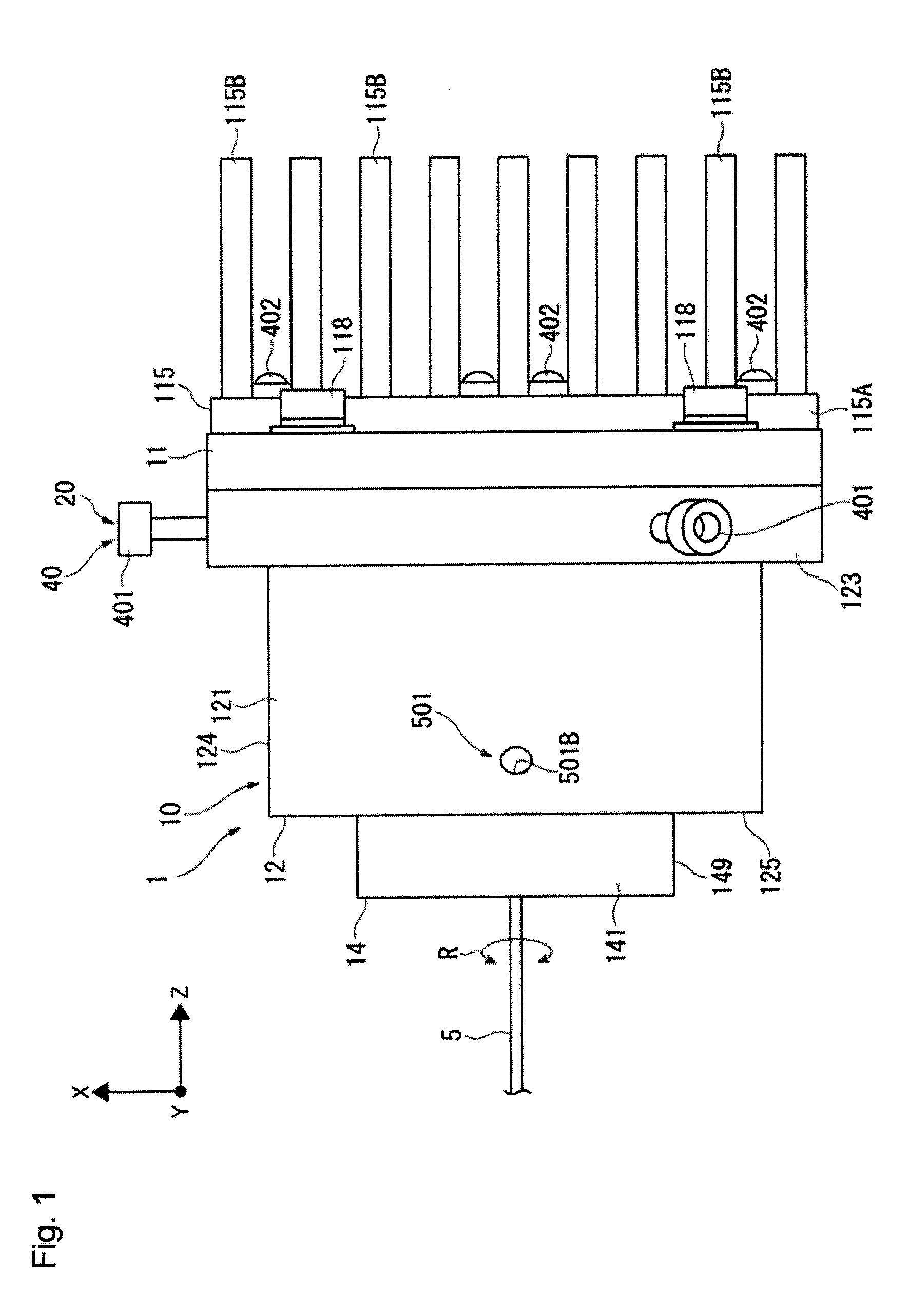
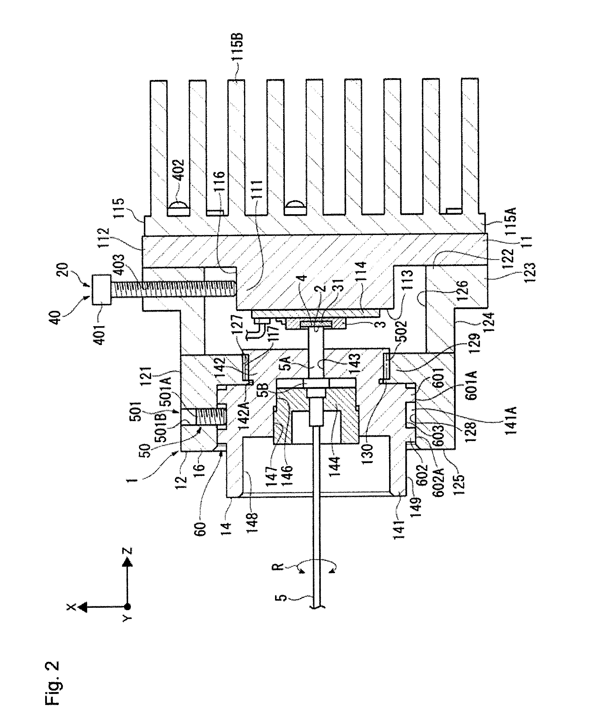
[0026]In FIGS. 1 and 2, a light source apparatus 1 according to a first embodiment of the present disclosure includes a light source 3, which includes a light-emitting surface 2; an optical fiber 5, which includes a light-receiving surface 4; a positioning mechanism 20 positioning the light source 3 and the optical fiber 5 in a state where the light-emitting surface 2 and the light-receiving surface 4 face each other; and a casing 10 holding the above components. In the light source apparatus 1, light emitted from the light-emitting surface 2 of the light source 3 is received on the light-receiving surface 4 of the optical fiber 5.

[0027]The casing 10 includes a base 11 holding the light source 3 on a surface thereof, a case 12 joined to the base 11 and covering the light source 3, and a holder 14 holding an end of the optical fiber 5. A sleeve 16 is formed on the case 12 to mount the holder 14.

[0028]The light source 3 is configured by an LED chip having an LED 31 performing surface ...

second embodiment

[0070]FIG. 4 illustrates a second embodiment according to the present disclosure. In the present embodiment, the basic configuration of the light source apparatus 1 is similar to that described above in the first embodiment. Accordingly, identical reference numerals are used for similar structures, and duplicative descriptions are omitted. In contrast to the use of the three position adjustment screws 401 in the first embodiment, the light source apparatus 1 of the present embodiment uses four position adjustment screws 401A positioned at equal intervals from each other in the circumferential direction, herein, at equiangular intervals (90°), as shown in FIG. 4. In the light source apparatus 1 according to the present embodiment configured in this way, rotation of each of the position adjustment screws 401A can displace the base 11 in the X-Y axis direction. Accordingly, an advantage similar to that described above in the first embodiment can be achieved in the present embodiment as...

third embodiment

[0071]FIG. 5 illustrates the third embodiment according to the present disclosure. In the present embodiment, the basic configuration of the light source apparatus 1 is similar to that described above in the first embodiment. Accordingly, identical reference numerals are used for similar structures, and duplicative descriptions are omitted. The light source apparatus 1 according to the present embodiment includes, as shown in FIG. 5, a refractive index matching material 70 as a medium correcting a refractive index, interposed between the light-emitting surface 2 of the light source 3 and the light-receiving surface 4 of the optical fiber 5. Therefore, by correcting the refractive index using the refractive index matching material 70, reflection of light by the light-receiving surface 4 of the optical fiber 5 can be reduced. An advantage similar to that described above in the first embodiment can be achieved with the present embodiment, and reflection of light by the light-receiving ...


PUM


Abstract

A light source apparatus includes a light source, an optical fiber, and a positioning mechanism. The positioning mechanism is configured with a planar position adjustment mechanism, an axial line position adjustment mechanism, and an orientation maintaining mechanism. The planar position adjustment mechanism adjusts a position of the optical fiber in a direction following the light-emitting surface. The axial line position adjustment mechanism adjusts the position of the optical fiber in a direction intersecting with the light-emitting surface. The orientation maintaining mechanism holds the optical fiber in a state where an axis direction of the optical fiber lies in a predetermined intersecting direction with respect to the light-emitting surface.

Description

CROSS-REFERENCE TO RELATED APPLICATIONS [0001]The present application claims priority under 35 U.S.C. §119 of Japanese Application No. 2013-106978, filed on May 21, 2013, the disclosure of which is expressly incorporated by reference herein in its entirety.BACKGROUND OF THE INVENTION [0002]1. Field of the Invention[0003]The present invention relates to a light source apparatus channeling light from a light source into an optical fiber.[0004]2. Description of Related Art[0005]In recent years, an LED light source apparatus has been used which takes an LED (light-emitting diode) as a light source and channels light from the LED into an optical fiber. In the LED light source apparatus currently in widespread use, light emitted from a light-emitting surface of the LED is collected by a lens and received on a light-receiving surface of the optical fiber. In order to improve optical connection efficiency, the light-emitting surface of the LED and the light-receiving surface of the optical ...

Claims


Application Information

Patent Timeline
IPC IPC(8): F21V8/00
CPCG02B6/0006G02B6/4226G02B6/4298
Inventor MASUDA, NORIHIKOISHIGE, MASASHI
Owner MITUTOYO CORP
Why Eureka
Try Eureka