Method of repairing a fibre composite solid member

a fibre composite solid member and fibre composite technology, applied in the direction of lamination, layered products, etc., can solve the problems of difficult repair process, few spare moulds, and occasional damage to moulds, so as to achieve shorter maintenance downtime and repair more efficiently

Active Publication Date: 2011-02-17
VESTAS WIND SYST AS
View PDF12 Cites 19 Cited by
  • Summary
  • Abstract
  • Description
  • Claims
  • Application Information

AI Technical Summary

Benefits of technology

[0004]It is an object of the present invention to provide a method of repairing a fibre composite solid member by which method the repair can be carried out more efficiently and thereby with a shorter downtime for maintenance than what is possible with presently known methods.

Problems solved by technology

A known problem is that the mould occasionally gets damaged e.g. due to small surface parts being torn off when a blade is removed from the mould after manufacturing, or due to accidental indents, cracks or scratches obtained during handling of the mould.
Since such a mould is typically expensive and takes up much storage space, the number of moulds at a manufacturing site is kept to a minimum, and no or very few spare moulds may be available if some are taken out of the production line for maintenance.
Such a repair process is difficult to carry out, especially on surfaces having double curvature.
The result of a repair process is therefore very dependent on the skills of the person carrying out the repair, and it is difficult to ensure that a desired quality is obtained.

Method used


Image

  • Method of repairing a fibre composite solid member
  • Method of repairing a fibre composite solid member
  • Method of repairing a fibre composite solid member

Examples


Embodiment Construction

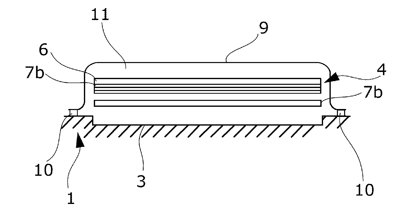
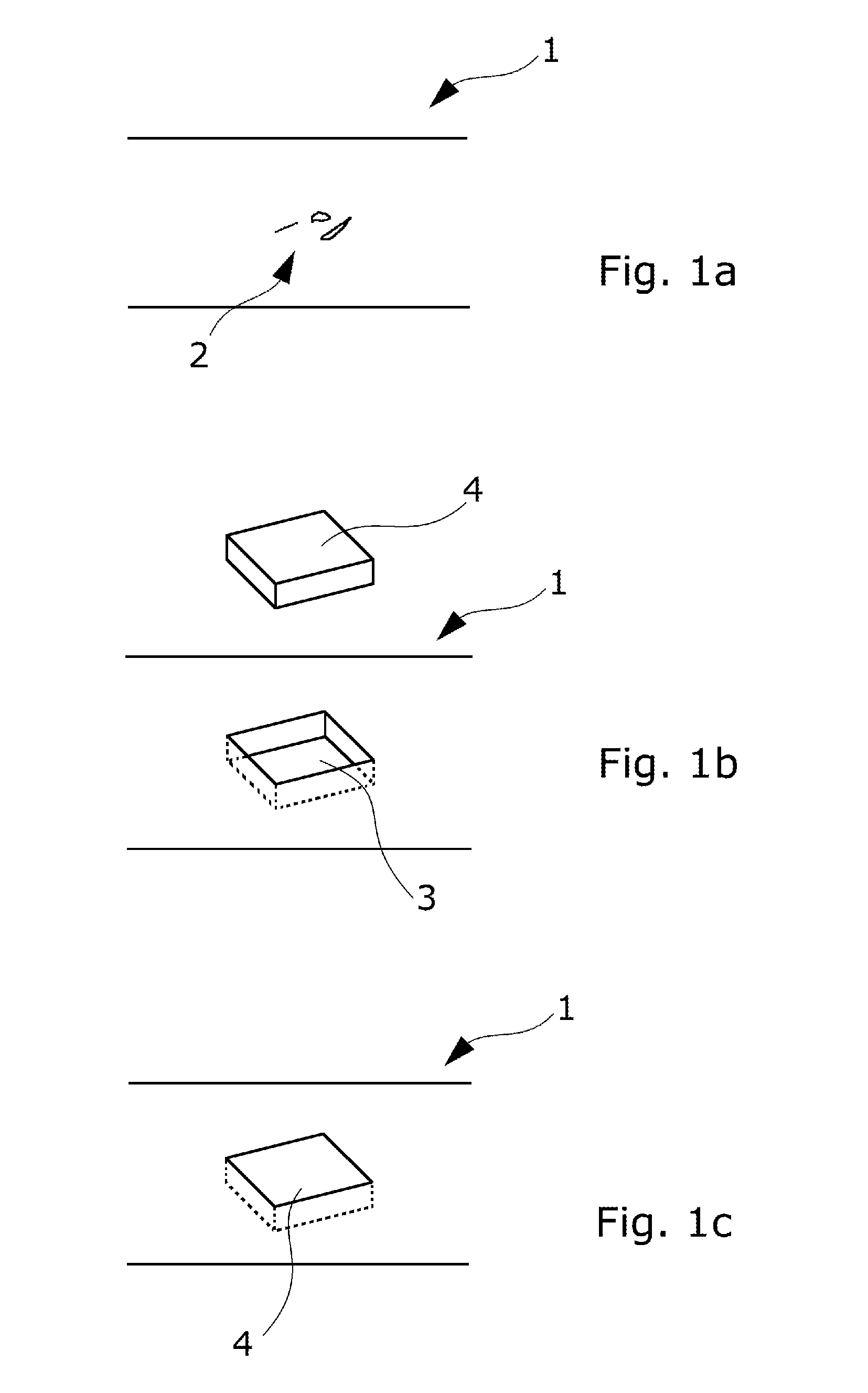
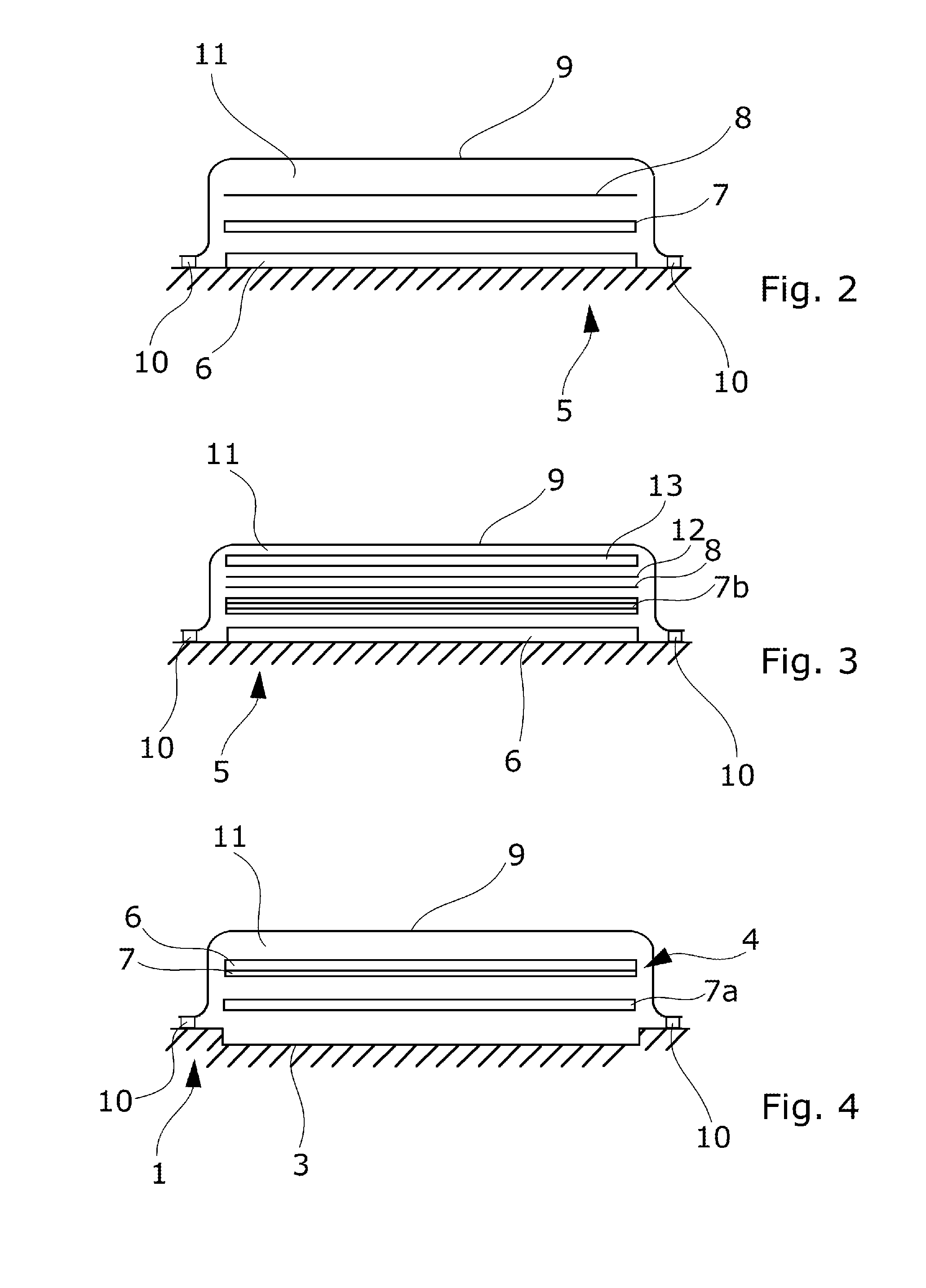
[0049]FIG. 1 shows schematically the overall idea of repairing a fibre composite solid member 1 having a locally deteriorated surface area 2; see FIG. 1a. The solid member could e.g. be a mould used in the manufacture of wind turbine blades or it could be a wind turbine blade. The deteriorated surface area 2 may e.g. have cracks or creases due to accidental impact. The repair typically only takes place in the outer finish layer which is not load-carrying. If the solid member 1 is a mould, the defects could also be due to small parts being torn off when a wind turbine blade is removed from the mould after manufacturing. FIG. 1b illustrates that a recess 3 has been made in the surface section comprising the locally deteriorated surface area 2. The recess 3 has a predefined depth and circumferential shape matching a repair patch 4 to be placed in the recess 3 in replacement of the removed material. FIG. 1c shows schematically a repaired surface section where the repair patch 4 has been...


PUM

PropertyMeasurementUnit
depthaaaaaaaaaa
depthaaaaaaaaaa
depthaaaaaaaaaa

Abstract

The present invention relates to a method of repairing a fibre composite solid member having a locally deteriorated surface area, such as having cracks or creases. The solid member may e.g. be a mould for the manufacturing of wind turbine blades or such blades. The method comprises machining a surface section comprising the locally deteriorated surface area in order to obtain a recess having a predefined depth and circumferential shape, placing a repair patch having a predefined thickness and circumferential shape matching the recess in the recess, and fastening the repair patch to the solid member by use of a binder material. At least some of the elastic and thermal properties of the repair patch and the binder material are so that after fastening, the repair patch and the binder material in combination have elastic and thermal properties which are substantially the same as the corresponding properties of the surface section before machining.

Description

FIELD OF THE INVENTION[0001]The present invention relates to a method of repairing a fibre composite solid member and in particular to a method comprising use of a repair patch.BACKGROUND OF THE INVENTION[0002]Fibre reinforced resin composites are used in the wind turbine industry e.g. for rotor blades. The manufacturing process typically comprises use of a mould to obtain the desired shape of the blades. A known problem is that the mould occasionally gets damaged e.g. due to small surface parts being torn off when a blade is removed from the mould after manufacturing, or due to accidental indents, cracks or scratches obtained during handling of the mould. Since such a mould is typically expensive and takes up much storage space, the number of moulds at a manufacturing site is kept to a minimum, and no or very few spare moulds may be available if some are taken out of the production line for maintenance. A known method of repairing a deteriorated surface area of such a mould is by g...

Claims


Application Information

Patent Timeline
Patent Type & Authority Applications(United States)
IPC IPC(8): B32B43/00
CPCB29C73/10B29C73/30Y10T29/49732Y10T29/49734B29C2073/264
Inventor STENBAEK, KNUD NIELSENOLESEN, ALEXSCHRODER, HENNING
Owner VESTAS WIND SYST AS
Why Eureka
Try Eureka