Apparatus for filling a cavity, filling station and method of filling a cavity

a technology for filling apparatuses and cavities, applied in the field of apparatus for filling cavities, filling stations and methods of filling cavities, can solve the problems of cigarette rods and filter rods being handled in enormous numbers, physical delicateness and fragile, etc., to simplify the mechanical construction of the filling station, reduce the number of unwanted “voids, and reduce the need for space.

Inactive Publication Date: 2014-03-04
INT TOBACCO MACHINERY POLAND
View PDF16 Cites 10 Cited by
  • Summary
  • Abstract
  • Description
  • Claims
  • Application Information

AI Technical Summary

Benefits of technology

[0040]It will be appreciated that, with the present invention, there need be no relative movement, during the cavity-filling process, between the hopper and the storage device. Instead, what is envisaged is an absence of such relative movement, during filling, between the hopper and the storage device, the requisite movement to achieve gentle filling being accomplished instead by the downward and upward stroke of the inventive cavity-filling device. This cavity-filling device, in preferred embodiments, functions not only as a shutter in the floor of the hopper, but also as a device for lowering product articles from the hopper to the floor of the cavity of the storage device, with virtually no unmanaged free fall under gravity apart from any residual “settling” of articles below the filling device, into their desired symmetrical close-packed arrangement in the storage cavity. Not only that, but the upward stroke of the cavity-filling device, through the bed of product items filling the cavity, has the potential to ease the product items into the desired close-packed arrangement, and minimise the number of unwanted “voids” and free space between the articles in the cavity below the filling device.
[0041]It will also be appreciated by skilled readers that the cavity-filling device can be the only sub-assembly that moves during the filling of the storage device. One can envisage that the space requirements needed for the reciprocating cavity-filling device might be relatively modest. Further, one can envisage a simplified mechanical construction of the filling station, and rapid exchange of a cavity-filling device that is in need of maintenance or repair, with very little downtime in the filling station as such.
[0042]Applicant has found it advantageous to select for the bars of the first set a cross-section which is generally rectangular (although the four perpendicular corners of the cross-section will be rounded to some extent, as appropriate to minimise physical damage to the articles being handled). Applicant has also found it effective to arrange for these bars of the first set, with non-circular cross-section, to be mounted all for simultaneous oscillatory rotatory motion about a relatively small angle. This assists the smoothness of throughflow of the product articles past the bars of the first set during the upstroke of the cavity-filling device. Furthermore, the gentle impulse given to the rod-shaped articles during the oscillatory motion can be just enough to assist the rods into a disposition closer to the ideal symmetrical close packed arrangement below the cavity-filling device.
[0043]However, a range of other cross-sections are contemplated. Circular cross-sections with a grooved or ridged surface might assist an oscillatory movement of the bars to jiggle the rod-shaped articles into a close-packed array. Non-circular cross-sections with a greater number of faces than four might work as well, or better, than 4-sided bars. While oscillatory rotatory movement is presently preferred, other forms of movement of the bars of the first set, such as small amplitude vibration about their median positions in the bar array, might be equally or more effective to assist through flow of rod articles and their close packing beneath the filling device. Specifically, we envisage small amplitude oscillation, up and down, in the bars of the first set, as a way to defeat any incipient tendency of the rods to “bridge” between and above any particular adjacent pair of bars of the first set.
[0044]Conversely, the bars of the second set advantageously have a circular cross-section. They are not well-placed on the upstroke to assist the rod articles into a close packed disposition. Giving them a smooth circular cross-section is one design option. Another is to give them a trapezium cross-section with a pair of parallel faces serving as horizontally arranged upper and lower major surfaces. Conveniently, the bars of the second set are not required to rotate at all during the downstroke or the upstroke, but only to move, in the intervals between the upward and downward strokes, laterally relative to the bars of the first set. This is conveniently accomplished by mounting all the bars of the second set on a common beam that is arranged to move horizontally and laterally below the bars of the first set, between the open and closed configurations of the cavity-filling device.

Problems solved by technology

The tobacco industry presents specific challenges for handling a mass flow of articles.
Cigarette rods and filter rods are physically delicate and fragile, but are handled in enormous numbers, when manufacturing packs of cigarettes.

Method used


Image

  • Apparatus for filling a cavity, filling station and method of filling a cavity
  • Apparatus for filling a cavity, filling station and method of filling a cavity
  • Apparatus for filling a cavity, filling station and method of filling a cavity

Examples


Embodiment Construction

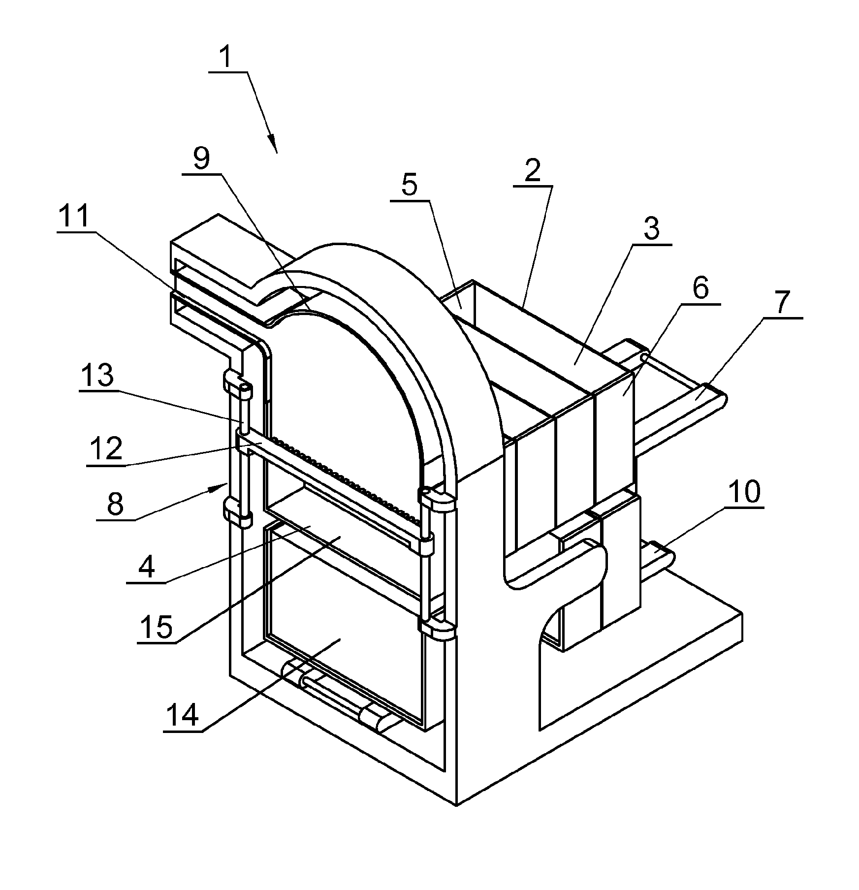
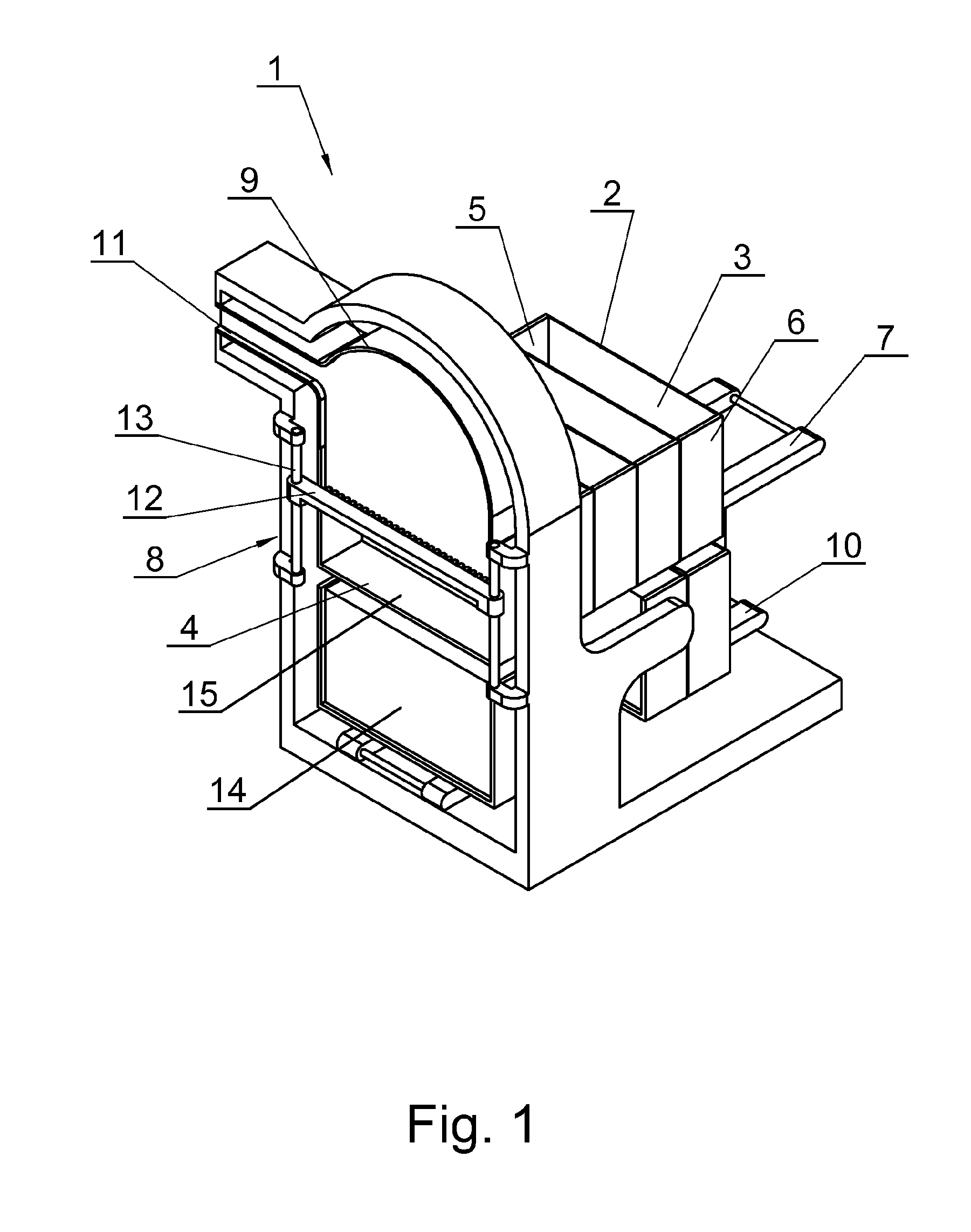
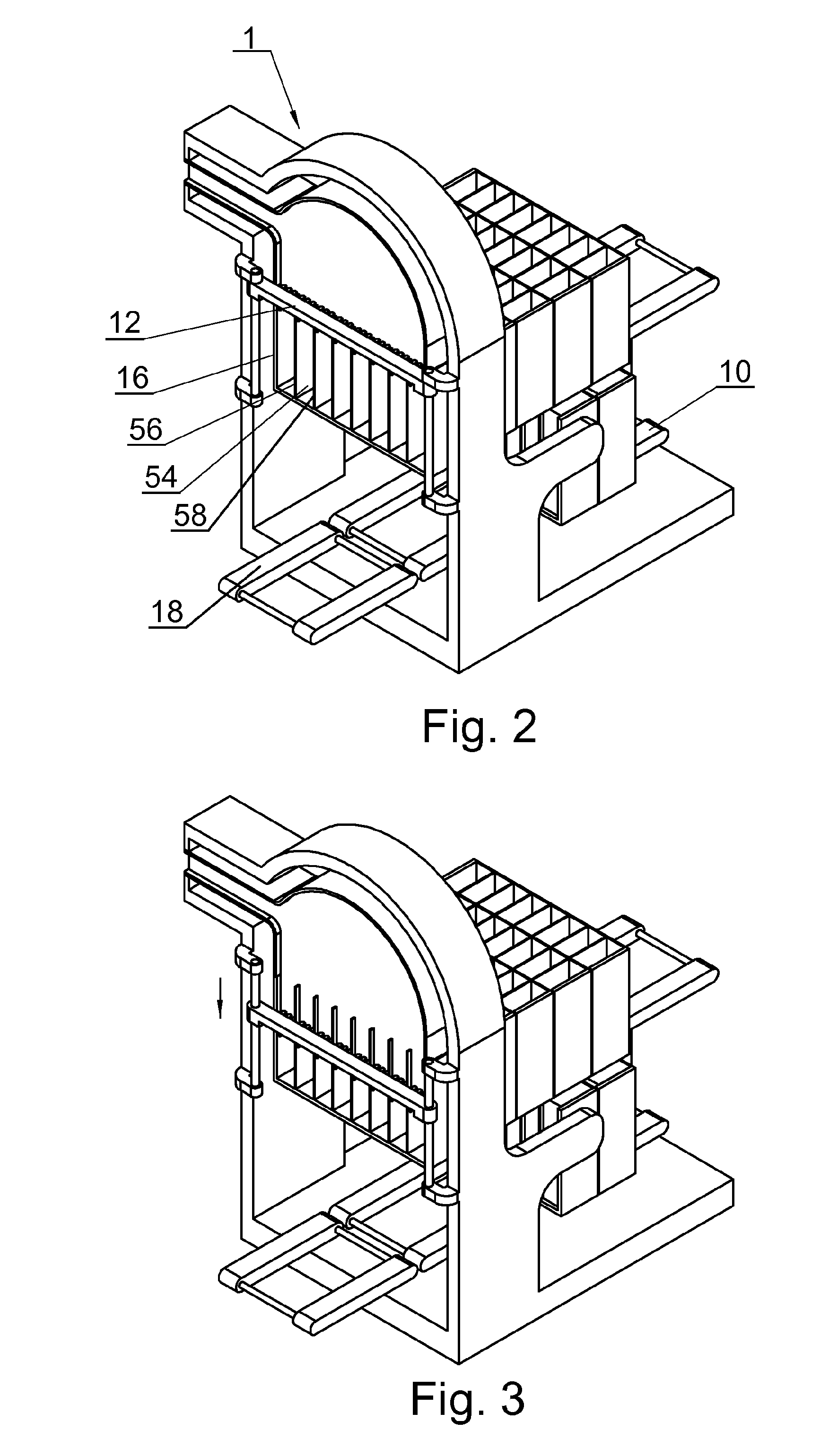
[0063]The filling station 1 in FIG. 1 exhibits an input zone in which empty trays 2 are presented for filling on the station. Each tray has a back wall 3 and parallel side walls 5 and 6 with a cavity in-between. Full trays are carried along on an input conveyor 7 to a filling region 8 of the filling station. The tray of FIG. 1 exhibits just a single cavity. Each tray has a base surface 4 that spans between the opposed side walls 5 and 6 of its single full width cavity. Empty trays are carried along on an input conveyor 7 to a filling region 8 of the filling station. A hopper 9 for rod-shaped articles such as cigarette rods or cigarette filter rods is fed from an input conveyor 11 and another input conveyor 7 brings empty trays to the filling station in which a filling device 12 is carried on vertical guides 13 so that it can perform an upstroke and a downstroke relative to the hopper 9. FIG. 1 shows a full tray 14 on the output conveyor 10, after having been lowered away from the fi...


PUM

PropertyMeasurementUnit
gravityaaaaaaaaaa
mass flowaaaaaaaaaa
speedaaaaaaaaaa

Abstract

Apparatus and method for filling under gravity from a hopper (9), a storage device (2) for articles that has the form of a columnar cavity between opposed side walls with a mass flow of mutually parallel rod-shaped articles descending from the hopper, a cavity-filling device (12) that alternates in use between a closed configuration that blocks a downward flow of the said articles through the device and an open configuration that allows flow of the articles through the device, the device being movable in translation, in alternate upward and downward strokes within the cavity, being in the closed configuration on the downward stroke and in the open configuration on the upward stroke.

Description

[0001]This invention relates to apparatus for filling a cavity, a filling station and method of filling a cavity, in particular apparatus for filling under gravity from a hopper, a storage device for articles, the storage device having a form of a columnar cavity between opposed side walls, with a mass flow of mutually parallel (or substantially mutually parallel) rod-shaped articles descending from the hopper.[0002]The apparatus is useful for filling a cavity with rod-shaped articles that are cigarette rods or cigarette filter rods or other tobacco products (such as cigars or cigarillos).[0003]The tobacco industry presents specific challenges for handling a mass flow of articles. Cigarette rods and filter rods are physically delicate and fragile, but are handled in enormous numbers, when manufacturing packs of cigarettes. To handle a mass flow of cigarette rods from a cigarette maker to a cigarette packer, it is conventional to employ a so-called “tray” for temporary storage of cig...

Claims


Application Information

Patent Timeline
Patent Type & Authority Patents(United States)
IPC IPC(8): B65G47/26A24C1/14B65B19/34
CPCA24C5/02A24C5/354
Inventor OWCZAREK, RADOSLAWGIELNIEWSKI, ADAM
Owner INT TOBACCO MACHINERY POLAND
Why Eureka
Try Eureka