Method and device for replacing objective parts

a technology of objective parts and replacement methods, applied in the direction of photomechanical equipment, instruments, cleaning using liquids, etc., can solve the problems of imposing a very high space requirement, affecting the effect of optical elements, so as to avoid the introduction of contaminants, short downtime, and effective and easy replacement methods

Inactive Publication Date: 2009-10-22
CARL ZEISS SMT GMBH
View PDF10 Cites 11 Cited by
  • Summary
  • Abstract
  • Description
  • Claims
  • Application Information

AI Technical Summary

Benefits of technology

[0013]It is therefore an object of the present invention to provide a method and a device to replace objective parts for the purpose of largely avoiding introduction of contaminants into the objective interior, wherein the replacement is to be conducted in an effective and easy way. Especially, rapid replacement of objective parts with short downtimes for the objective is to be made possible while the problems of the prior art are avoided.

Problems solved by technology

However, this imposes a very high space requirement.
When parts located in the highly clean, gas-flushed or evacuated objective interior are replaced, there is a problem that the process of replacement can introduce impurities into the objective.
Accordingly, unless further cleaning takes place, this means that hydrocarbons are present in the objective and can then enter into chemical reactions at undesirable regions, and so lead to deposits on the optical elements.
As a result, the imaging properties of the objective are impaired.
A further problem of replaceable components of the optical system of a lithography system is that particles adhering to the replacement parts can become detached from the replacement parts and precipitate on the surfaces of the optical elements, a fact which also impairs the imaging properties.
However, this approach has the disadvantage that, first, the contaminants are introduced into the objective interior and there is a risk that, on account of the subsequent cleaning, said contaminants are not completely removed from the objective interior, such that, for example, a device according to US 2006 / 0001854 A1 is required.
Furthermore, this approach means that the objective is inoperable for a long period because, during this time, cleaning takes place after the corresponding parts of the objective have been replaced.
Moreover, there is a risk that, in storage, tiny amounts of contaminants in the sealed atmosphere around the replaceable objective part will in turn lead to deposits.

Method used


Image

  • Method and device for replacing objective parts
  • Method and device for replacing objective parts
  • Method and device for replacing objective parts

Examples


embodiment 2

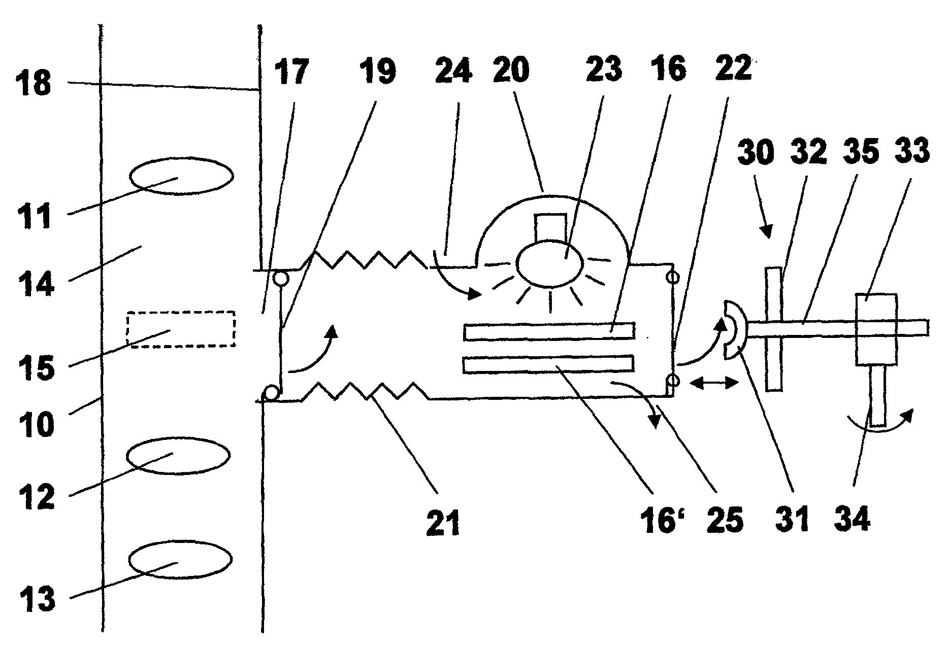
[0084]FIG. 3 shows a further embodiment of an inventive objective and a cleaning device 220 interacting with it. Again, , similar or identical components are provided with identical reference symbols, with, in turn, the reference numbers being 200 higher than in FIGS. 1 and 100 higher than the reference numbers of FIG. 2. Here, too, an additional description of components already discussed is eschewed.

[0085]FIG. 3 shows in addition to FIGS. 1 and 2 sealing elements 227 in the region where the cleaning device 220 is connected to the objective housing 218. In the simplest case, these may be O-rings or other tensioned elastic elements, such as metal seals, that guarantee a gastight seal. Alternatively, a leaky seal may be chosen if, by means of corresponding excess pressure in the objective 210 or the cleaning device 220, it is ensured that no foreign substances can gain entry into the objective 210 or the cleaning device 220.

[0086]Further, FIG. 3 shows that the handling device 230 can...

fourth embodiment

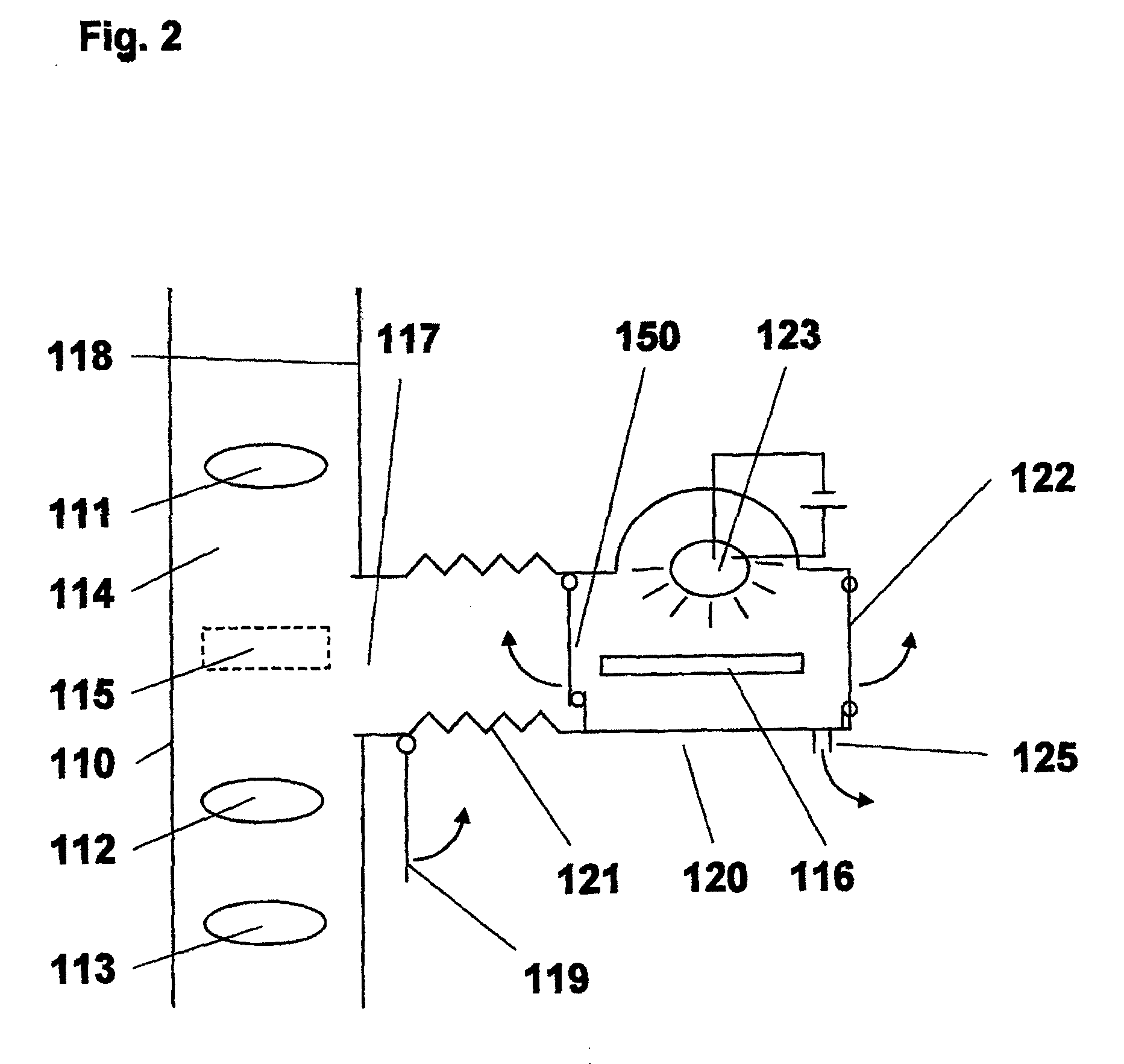
[0089]FIG. 4 shows a cleaning device 320 in cooperation with an objective 310, also in a schematic cross-section like the previous depictions of FIGS. 1 to 3.

[0090]Here, again, identical or similar components have identical reference numbers, but have been increased by 300 relative to FIG. 1, by 200 relative to FIG. 2 and by 100 relative to FIG. 3. Accordingly, here, too, an additional description of components already described is eschewed, and only additional components and parts are described in detail.

[0091]FIG. 4 shows a transport channel 340 as a component of the cleaning device 320, which channel, however, can be separated from the actual cleaning room 328, in which cleaning room the dashed lines represent the position of the replaceable objective part 316 during cleaning.

[0092]In the embodiment shown in FIG. 4, the transport channel 340 accommodates the handling device 330. However, the transport channel 340 can also be designed so as not to have a handling device.

[0093]The ...


PUM

PropertyMeasurementUnit
wavelengthsaaaaaaaaaa

Abstract

A method and a device for replacing objective parts, especially of a projection or illumination objective for microlithography in which an objective having an objective interior and objective parts provided therein is provided. At least one objective part is replaceably accommodated in the objective. Immediately prior to installation in the objective, the replaceable objective part is cleaned outside the objective interior in at least one cleaning room sealed off from the ambient atmosphere. Immediately after cleaning, the replaceable objective is installed in the objective without contact with the normal ambient atmosphere.

Description

[0001]This is a Continuation of International Application PCT / EP2007 / 061563, with an international filing date of Oct. 26, 2007, which was published under PCT Article 21(2) in German, and the complete disclosure of which, including amendments, is incorporated into this application by reference.FIELD OF AND BACKGROUND OF THE INVENTION[0002]The present invention relates to a method and a device for replacing objective parts, especially of a projection or illumination objective for microlithography.[0003]Modern lenses in lithography increasingly have replaceable or exchangeable elements, such as replaceable or exchangeable lenses, filters, diaphragms and the like. US 2006 / 0176460 A1 describes, for example, an EUV (extreme ultraviolet) lithography system having optical elements, such as mirrors and the like, which are individually selectable for use, wherein the optical elements are not replaced, in the sense of being moved into and out of the objective, but rather are exchanged only in...

Claims


Application Information

Patent Timeline
Patent Type & Authority Applications(United States)
IPC IPC(8): G02B7/14B08B3/12B08B7/00B08B1/00
CPCG03F7/70808G03F7/70825G03F7/70833G03F7/70916Y10T29/49723G03F7/70975B08B3/12B08B7/0035B23P6/00G03F7/70925
Inventor GEUPPERT, BERNHARDLIMBACH, GUIDOWOELFLE, HARALDDEUFEL, PETER
Owner CARL ZEISS SMT GMBH
Why Eureka
Try Eureka