Combination measuring device

a measuring device and comb technology, applied in the direction of measuring devices, instruments, special-purpose weighing apparatuses, etc., can solve the problems of reducing the efficiency of the conveyance of articles by the feed trough, compromising the stability of the supply of articles from the feed trough to the pool hopper, and reducing the diameter of the dispersing section. , to prevent the stability of the supply of articles, increase the width of the trough, and reduce the diameter of the dispersing section

a measuring device and comb technology, applied in the direction of measuring devices, instruments, special-purpose weighing apparatuses, etc., can solve the problems of reducing the efficiency of the conveyance of articles by the feed trough, compromising the stability of the supply of articles from the feed trough to the pool hopper, and reducing the diameter of the dispersing section. , to prevent the stability of the supply of articles, increase the width of the trough, and reduce the diameter of the dispersing section

US20110036645A1Active Publication Date: 2011-02-17ISHIDA CO LTD

Image

  • Combination measuring device
  • Combination measuring device
  • Combination measuring device

Examples


Embodiment Construction

[0036]An embodiment of the present invention will now be described in detail with reference to the drawings. Elements affixed with identical labels on different drawings represent elements that are identical or equivalent.

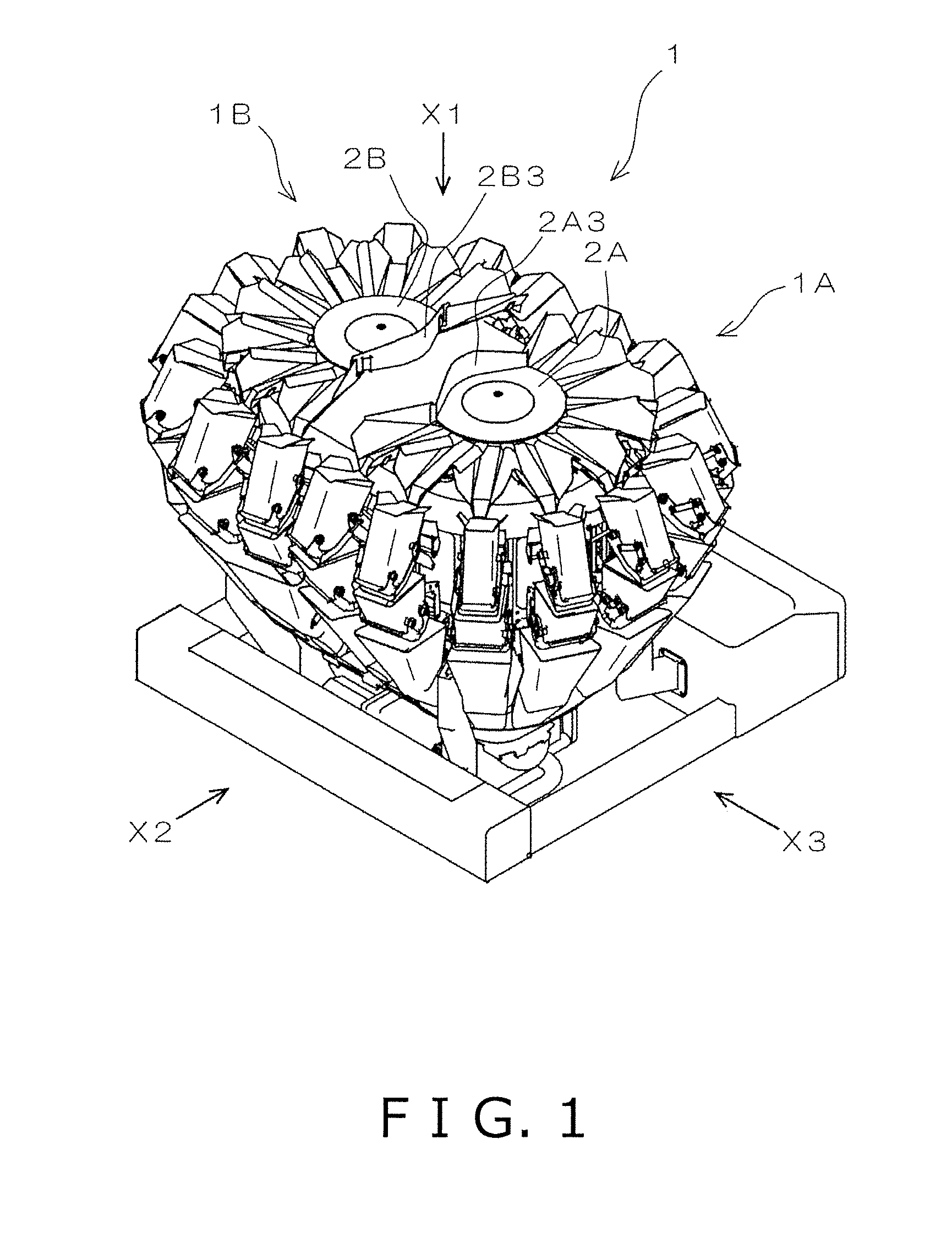
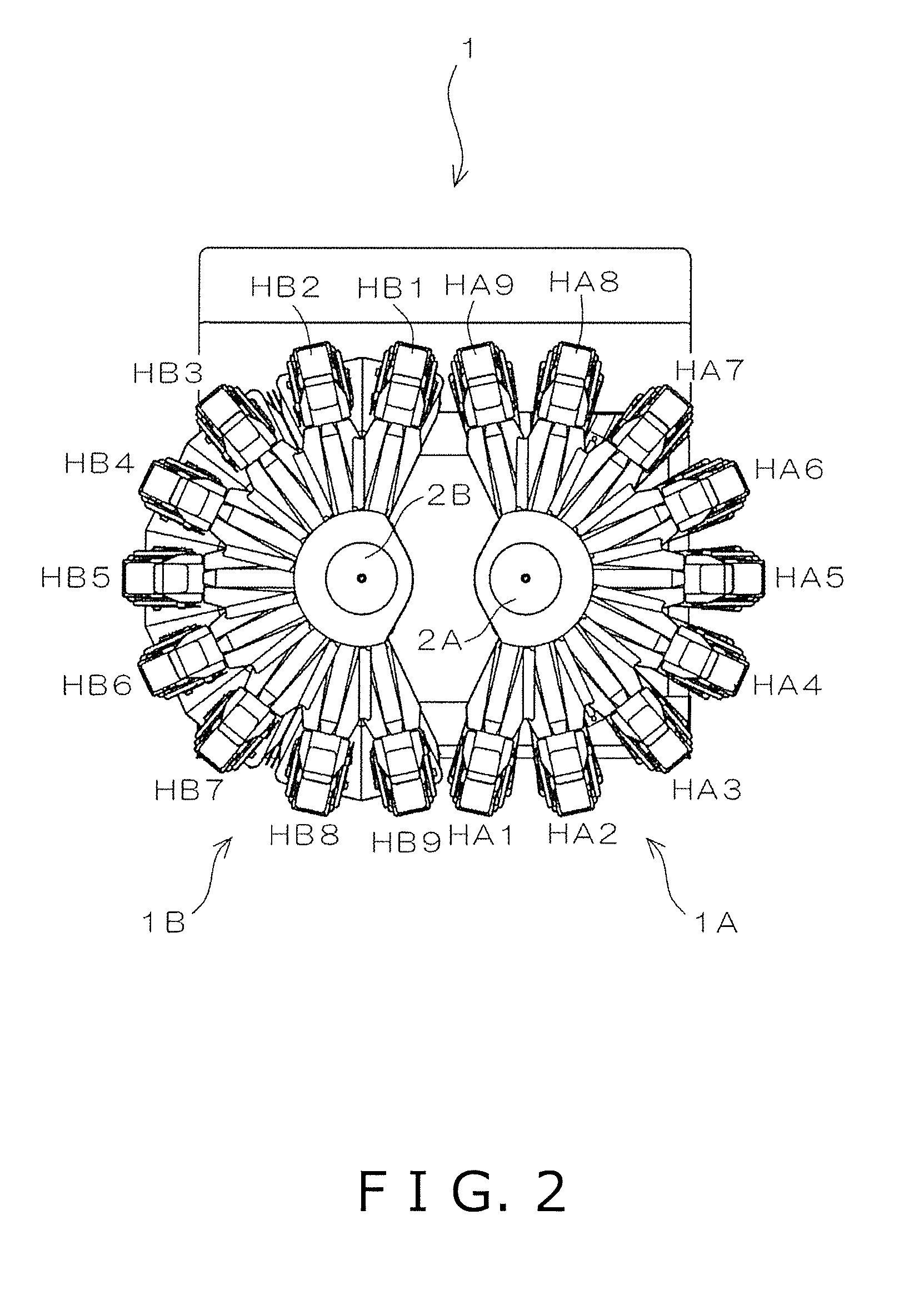
[0037]FIG. 1 is a perspective view showing an overall configuration of a combination measuring device 1 according to an embodiment of the present invention. FIG. 2 is a top view showing the combination measuring device 1 viewed from the direction of arrow X1 shown in FIG. 1; FIG. 3 is a front view showing the combination measuring device 1 viewed from the direction of arrow X2 shown in FIG. 1; and FIG. 4 is a side view showing the combination measuring device 1 viewed from the direction of arrow X3 shown in FIG. 1.

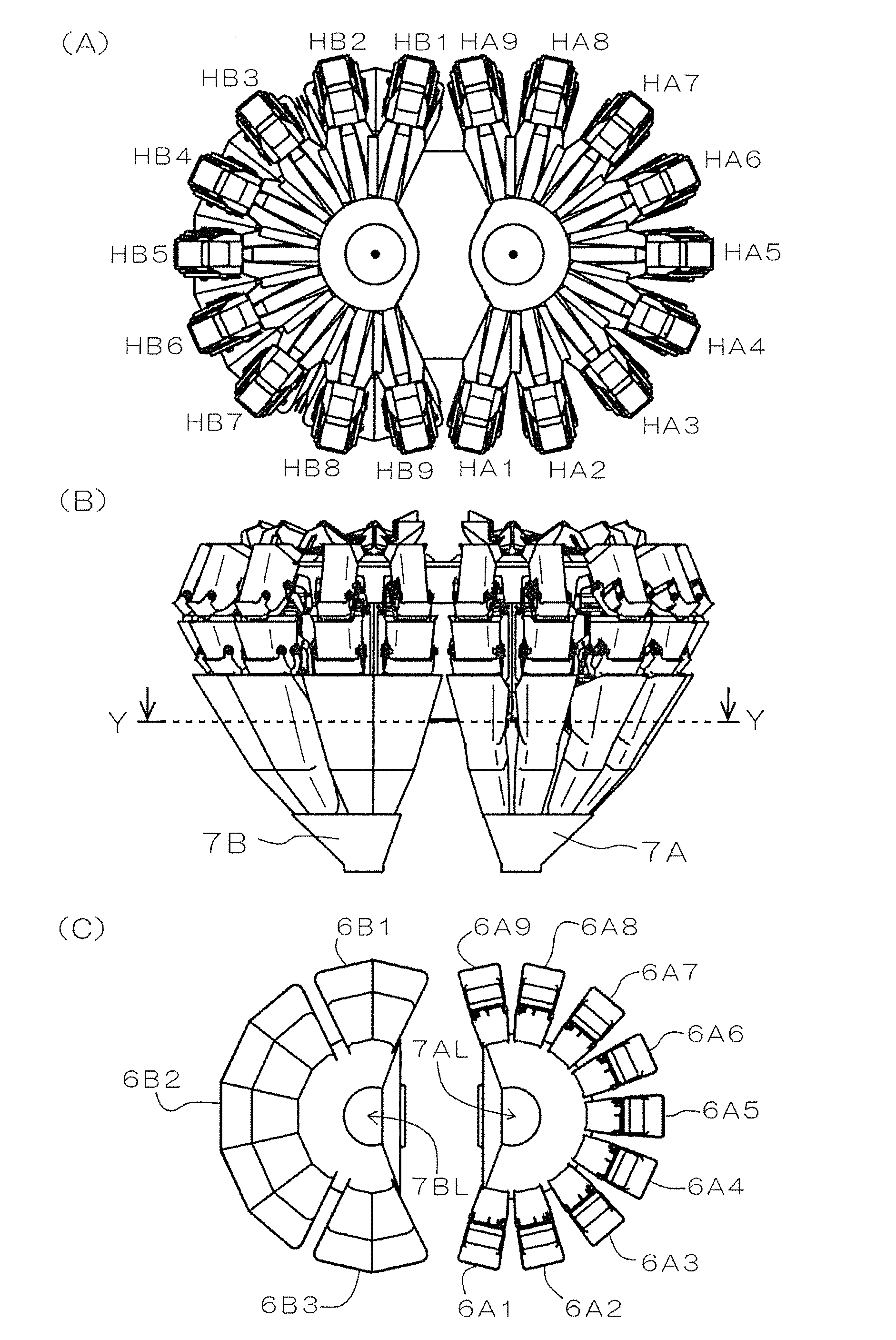
[0038]As shown in FIGS. 1 through 4, the combination measuring device 1 comprises a combination measuring unit 1A and a combination measuring unit 1B. As shown in FIGS. 1 and 2, the combination measuring unit 1A has a dispersing table 2A, and the combinat...


PUM


Abstract

A combination measuring device has a combination measuring unit. The combination measuring unit has a dispersing section configured to radially disperse articles loaded thereinto from above, a plurality of head sections configured to receive the articles from the dispersing section, and an assembling section configured to assemble the articles, which are contained in hoppers of one or more of the head sections selected according to a target weight. The head sections are arranged on a line formed by cutting away a circular arc from a circle surrounding the dispersing section.

Description

CROSS-REFERENCE TO RELATED APPLICATIONS[0001]This national phase application claims priority to Japanese Patent Application No. 2008-107499 filed on Apr. 17, 2008 and Japanese Patent Application No. 2008-108419 filed on Apr. 18, 2008. The entire disclosures of Japanese Patent Application Nos. 2008-107499 and 2008-108419 are hereby incorporated herein by reference.TECHNICAL FIELD[0002]The present invention relates to a combination measuring device.BACKGROUND ART[0003]An example of a combination measuring device relating to background art is disclosed in Japanese Examined Utility Model Application Publication No. 4-41304. The combination measuring device comprises a dispersing table; fourteen feed troughs arranged at regular intervals on a circle surrounding the dispersing table; fourteen pool hoppers, which being respectively provided below distal end portions of the feed troughs; and fourteen measuring hoppers, which being respectively provided below the pool hoppers. In other words...

Claims


Application Information

Patent Timeline
17 Feb 2011
Publication
US20110036645A1
IPC
G01G19/387
CPC
G01G19/393; G01G13/026
Inventors
KAGEYAMA, TOSHIHARU; KISHIKAWA, MIKIO