
Printing plate holding apparatus

a technology for holding apparatus and printing plate, which is applied in the direction of printing press, printing press parts, printing press, etc., can solve the problems of difficult to ascertain the position of the printing plate, bounces (vibrations), and difficult to fasten the printing plate with greater certainty, so as to reduce bounces (vibrations) and noises, increase the width of the groove, and reduce the effect of bounces

Inactive Publication Date: 2017-07-11
MIYAKOSHI PRINTING MACHINERY
View PDF16 Cites 0 Cited by
  • Summary
  • Abstract
  • Description
  • Claims
  • Application Information

AI Technical Summary

Benefits of technology

The present invention provides a printing plate holding apparatus that can securely hold a printing plate on a plate cylinder during high-speed printing operations. This results in reduced bounces and noises in the groove of the printing plate, and increases the certainty of fastening the printing plate. The apparatus is suitable for printing plates that need to be firmly held, such as on a sleeve cylinder that requires weight reduction.

Problems solved by technology

This technique, however, in which the grip leading and trailing ends of a printing plate are inserted merely in a groove has been uncertain whether the printing plate is firmly held in position.
While JP 2012-166569 A and JP 2002-326341 A show that press fitting members of metal, rubber, resin or leaf spring are added and press fitted into the groove for securing the printing plate, it has been difficult to ascertain that the press fitting members have been press fitted in a whole section in the width direction.
Also, a need to increase the groove width by an amount of the thicknesses of such press fitting members has caused bounces (vibrations), noises and printing obstacles to occur in the groove while the plate cylinder is being rotated at high printing speed.

Method used


Image

  • Printing plate holding apparatus
  • Printing plate holding apparatus
  • Printing plate holding apparatus

Examples


Embodiment Construction

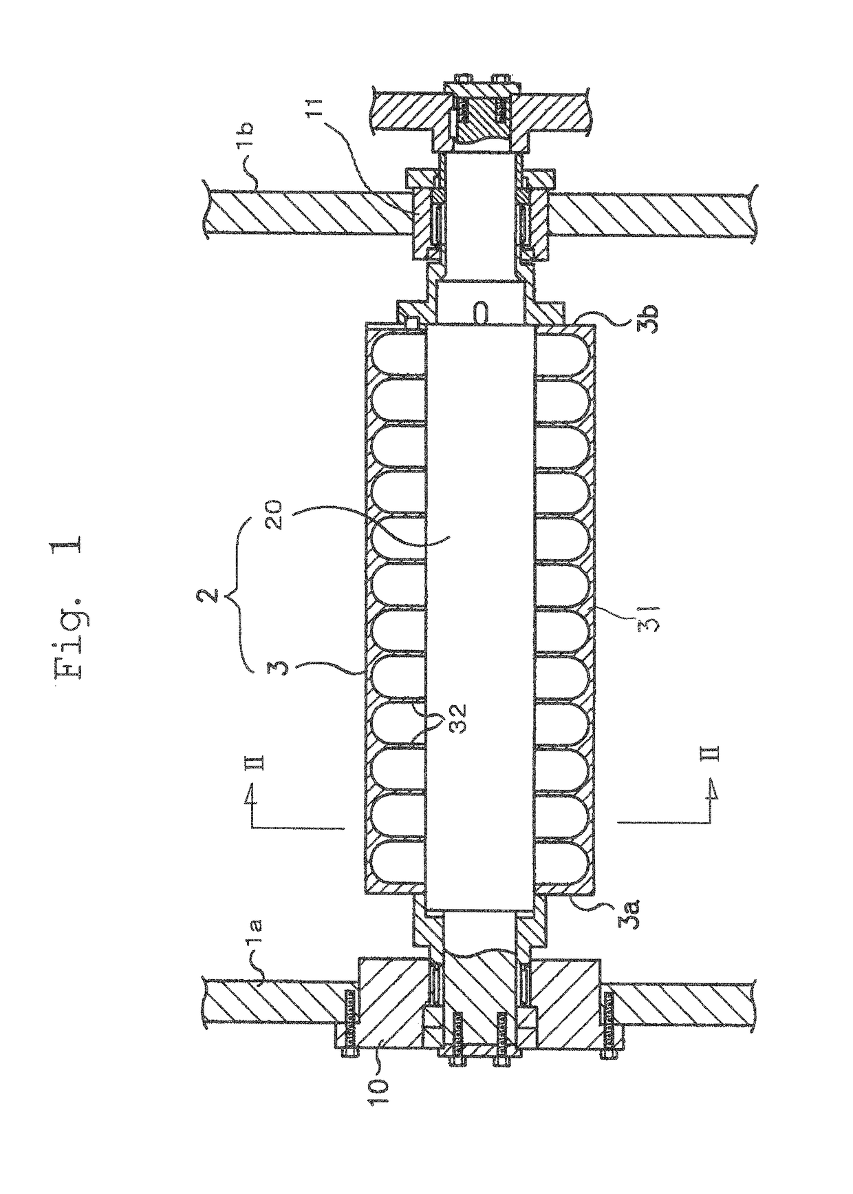
[0015]FIG. 1 shows a plate cylinder 2. The plate cylinder 2 consists of a rotating shaft 20 rotatably supported by bearing members 10 and 11 mounted on main frames 1a and 1b, and of a sleeve cylinder 3. The sleeve cylinder 3 comprises a cylinder body 33 having a plurality of ribs 32 in the form of centrally opened annular disks formed on an inner peripheral surface of a cylinder body 31 and axially spaced apart from one another. The sleeve cylinder 3 is removably mounted on the rotating shaft 20 so that it can be fitted on, and extracted from, the rotating shaft 20.

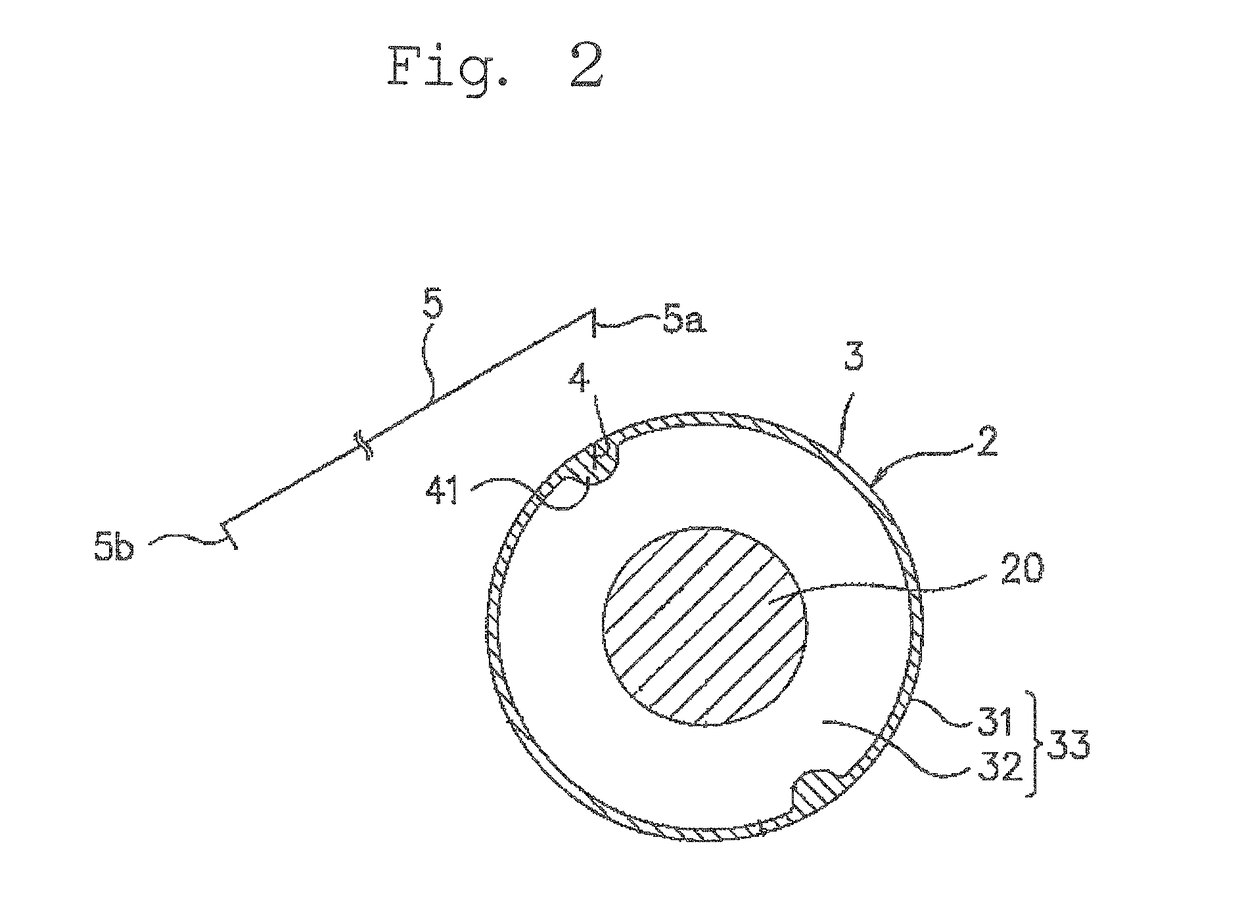
[0016]As shown in FIG. 2, the sleeve cylinder 3 (cylinder body 33) for the plate cylinder 2 is formed on its outer peripheral surface with a plate insertion groove 4 which extends axially and into which a grip leading end 5a and a grip trailing end 5b of an insertable printing plate 5 may be inserted. And, the grip leading end 5a of the insertable printing plate 5 is inserted into the plate insertion groove 4 as shown in ...


PUM


Abstract

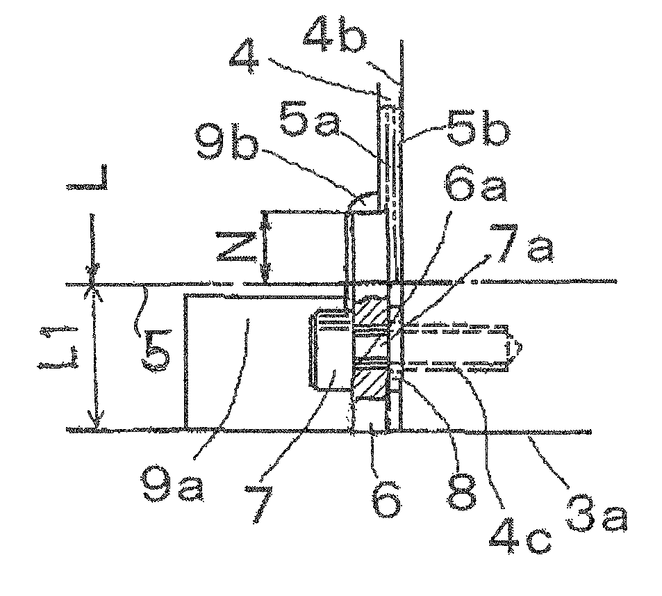
A printing plate holding apparatus is provided which during a high speed printing operation reduces vibrations and noises caused in a groove for having a grip leading end and a grip trailing end of a printing plate inserted therein, which can fasten the printing plate with greater certainty, and which is suitable for the printing plate to be held securely on such as a sleeve cylinder whose weight reduction is demanded.It is a printing plate holding apparatus in which a printing plate 5 wound on a plate cylinder 2 is to be held securely thereon in a rotary press, the apparatus having a plate insertion groove 4 formed on an outer peripheral surface of the plate cylinder 2 and extending axially of the plate cylinder 2 for receiving a grip leading end 5a and a grip trailing end 5b of the printing plate 2, and comprising a printing plate retainer plate 6 and a tap bolt 7 for bringing both widthwise lateral end portions of the grip leading and trailing ends 5a and 5b of the printing plate into overlapping each other in the plate insertion groove 2 and for pressing and fastening them against a constraint surface 4b with which the grip trailing end 5b is in contact, in the plate insertion groove 4.

Description

TECHNICAL FIELD[0001]The present invention relates to a printing plate holding apparatus whereby a printing plate wound on a plate cylinder is held securely thereon in a rotary press.BACKGROUND ART[0002]A sleeve cylinder exchangeable variable printer in which a printing images different in a vertical length are printed on a continuous web of paper is known from JP 2014-91301 A. Printing machines of this sort have been designed to exchange sleeve cylinders in a manual operation. Needs therefore arise to reduce the thickness of a sleeve cylinder as thin as possible in order to reduce its weight. The patent document mentioned above shows in FIGS. 4 and 5, and describes in connection therewith, an insertable printing plate which uses no plate clamping or winding bar but in which a grip leading end and a grip trailing end of the printing plate may be inserted simply in a groove on the sleeve cylinder for mounting the printing plate thereon.[0003]This technique, however, in which the grip...

Claims


Application Information

Patent Timeline
Patent Type & Authority Patents(United States)
IPC IPC(8): B41F27/12B41F27/10
CPCB41F27/10B41F27/125B41F27/1225B41F27/1262B41F27/12
Inventor FUJIWARA, REISHITOMAKI, HITOSHIODASHIMA, KAZUMI
Owner MIYAKOSHI PRINTING MACHINERY
Learn More