Cycloidal reducer

一种减速机、摆线的技术,应用在机械设备、传动装置、齿轮传动装置等方向,能够解决空程现象、组装效率降低、组装时间拉长等问题,达到增加刚性及定位精度、避免空程现象、减少碰撞噪音的效果

Active Publication Date: 2020-09-15
HIWIN TECH
View PDF8 Cites 0 Cited by
  • Summary
  • Abstract
  • Description
  • Claims
  • Application Information

AI Technical Summary

Problems solved by technology

However, since the side walls of the groove of the cycloid wheel, the side wall of the output element groove and the side wall of the cross Odan are all parallel to the axial direction, the rolling elements are first placed on the groove side of the cycloid wheel during assembly. Put the cross-oldan on the wall, or put the rolling element on the side wall of the cross-oldan first and then put the output element. Both methods are very easy to collide with the rolling element during assembly, which will not only cause the rolling element It must be reassembled due to overturning, resulting in reduced assembly efficiency and prolonged assembly time, and may cause damage to rolling elements, cycloidal wheels, cross Odan and output elements
[0004] Therefore, the current solution is to increase the width of the groove between the cycloidal wheel and the output element to facilitate the placement and assembly of the rolling elements, but in this way, not only will the gap between the elements be too large, but the transmission As the backlash increases, there will be problems such as lost motion during forward and reverse rotation, poor positioning accuracy, and increased collision noise.

Method used


Image

  • Cycloidal reducer
  • Cycloidal reducer
  • Cycloidal reducer

Examples


Embodiment Construction

[0032] In order to achieve the above-mentioned purpose and effect, the technical means and structure adopted by the present invention are described in detail below in conjunction with the accompanying drawings:

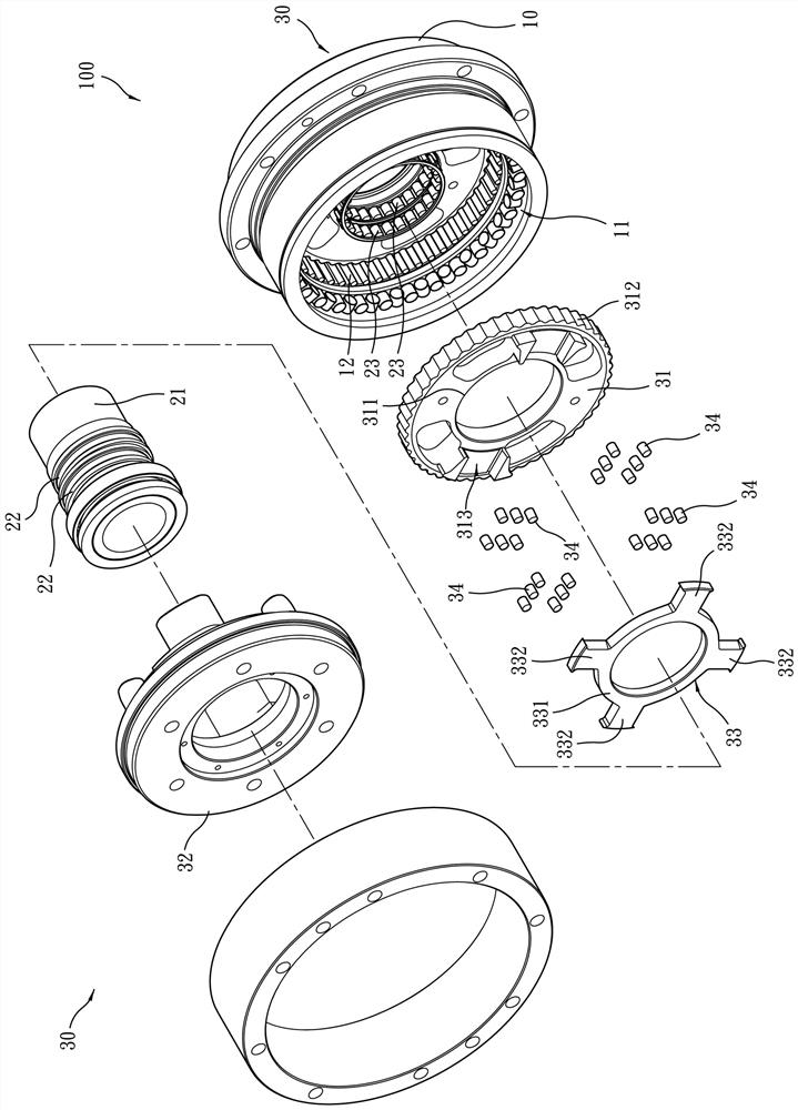
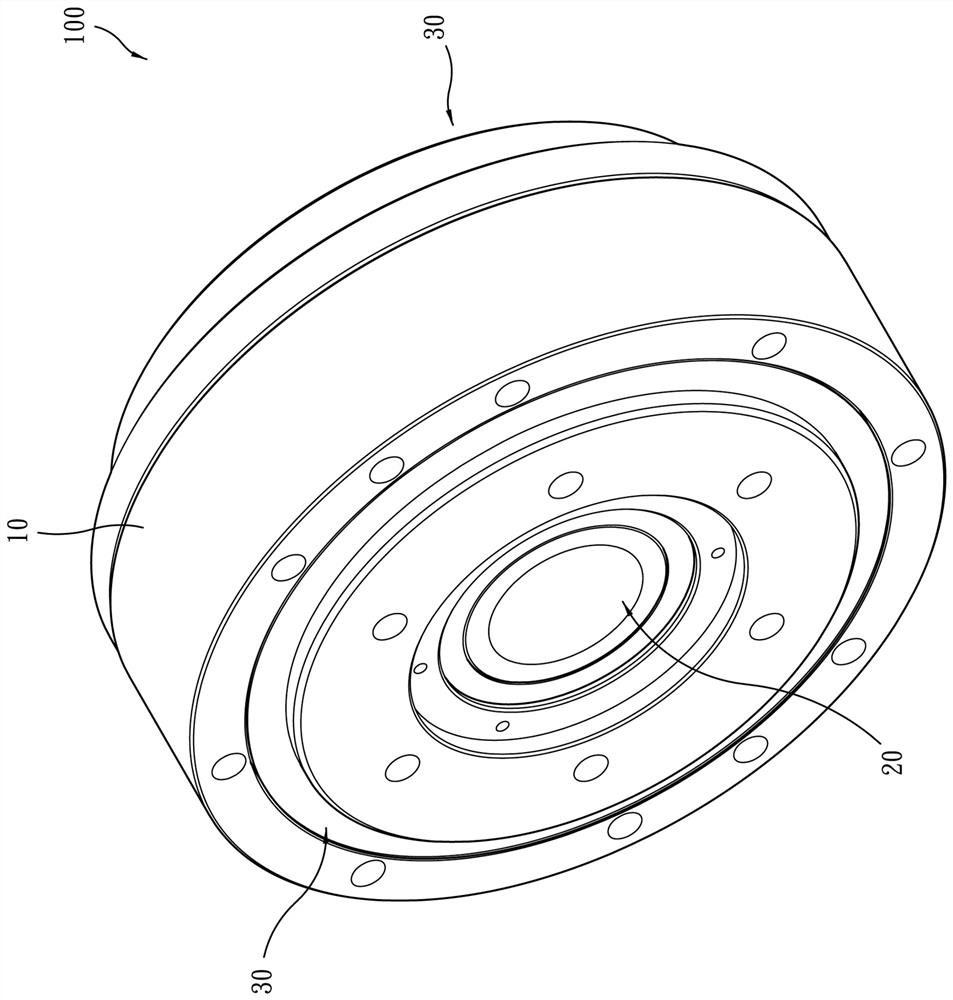
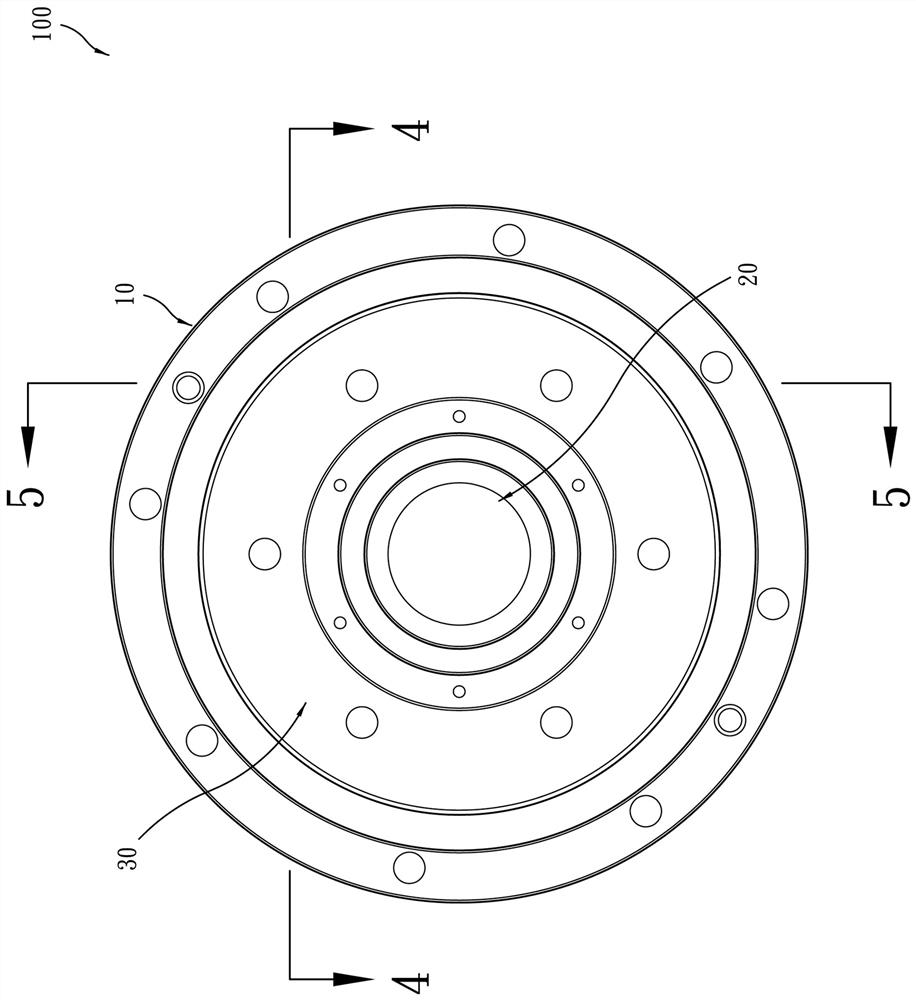
[0033] Such as Figure 1 to Figure 5 As shown, a cycloidal reducer 100 provided by a preferred embodiment of the present invention mainly includes a main body 10, an input shaft sleeve 20 and two deceleration output units 30, wherein:

[0034] The main body 10 has an axial assembly hole 11 and an annular inner tooth 12 formed on the inner peripheral surface of the axial assembly hole 11 .

[0035] The input shaft sleeve 20 has a shaft sleeve 21 , two eccentric sleeves 22 mounted on the shaft sleeve 21 and two bearings 23 respectively mounted on the eccentric sleeves 22 . The input sleeve 20 is placed in the axial assembly hole 11 of the main body 10 for inputting a deflection force.

[0036] The two deceleration output units 30 are arranged in the axial assembly hol...


PUM


Abstract

A cycloidal reducer, including a main body, an input shaft sleeve and two deceleration output units; each deceleration output unit has a cycloidal wheel, an output element, a cross Odan and several rolling elements, the cycloidal wheel Connected with the input bushing, the cycloidal wheel has several cycloidal wheel grooves, one side of the groove wall of each cycloidal wheel groove is an inclined plane, one end surface of the output element has several output element grooves, and the cross Odan has a The central ring part and four connecting parts protruding in a cross shape, one side wall of the connecting part is a slope, the two connecting parts of the cross Odan are placed in the groove of the cycloidal wheel, and the other two connecting parts are placed in the groove of the cycloidal wheel. In the output element groove of the output element, the rolling elements are respectively placed between the slope of the cycloid wheel and the slope of the cross Odan, and placed on the side wall of the coupling part between the groove wall of the output element groove of the output element and the cross Odan In order to achieve good assembly efficiency, reduce transmission backlash, avoid backlash phenomenon, good positioning accuracy and reduce collision noise and other effects.

Description

technical field [0001] The invention relates to a cycloid reducer, in particular to a cycloid reducer capable of improving assembly efficiency and reducing assembly cost. Background technique [0002] Cycloidal reducer is a common reduction mechanism. Its principle is to achieve deceleration output through eccentric input and gear difference transmission. [0003] However, the structure of the general cycloidal reducer is to use the cross Odan for non-coaxial connection transmission between the cycloid wheel and the output element (flange), so it must be connected between the cycloid wheel and the cross Odan and between the cross Odan Rolling elements (such as rollers) are set between the Dan and the output element to reduce power loss, that is, both the cycloidal wheel and the output element are provided with grooves for the cross Oudan to be set in, and the rolling element is positioned on the cross Oudan. Between the side wall of the cycloid wheel and the groove side wal...

Claims


Application Information

Patent Timeline
Patent Type & Authority Patents(China)
IPC IPC(8): F16H1/32F16H57/08
CPCF16H1/32F16H57/08F16D3/04F16H2001/326
Inventor 王政隆郑旭珉
Owner HIWIN TECH
Why Eureka
Try Eureka