Packing element

a packing element and sealing technology, applied in the field of improved packing elements, can solve the problems of affecting the sealing effect of the packing element, the failure of the sealing between the packing element and the casing, and the drawbacks of some conventional packers, and achieve the effect of reducing the setting pressur

Active Publication Date: 2011-02-17
RUBBERATKINS
View PDF12 Cites 20 Cited by
  • Summary
  • Abstract
  • Description
  • Claims
  • Application Information

AI Technical Summary

Benefits of technology

[0042]In one embodiment, a sealing element of the present invention is provided with external surface grooves which are adapted to close up when the element is compressed into engagement with a well bore wall. Provision of one or more external surface grooves which can close up as the sealing element is compressed into engagement with the wall allows for the contact pressure

Problems solved by technology

There are drawbacks associated with some conventional packers.
For example, it is known for the seal between the packing element and the casing to fail if the element has been set in a high temperature environment which subsequently cools.
It is also known for the seal to fail when the packer

Method used


Image

  • Packing element
  • Packing element
  • Packing element

Examples


first embodiment

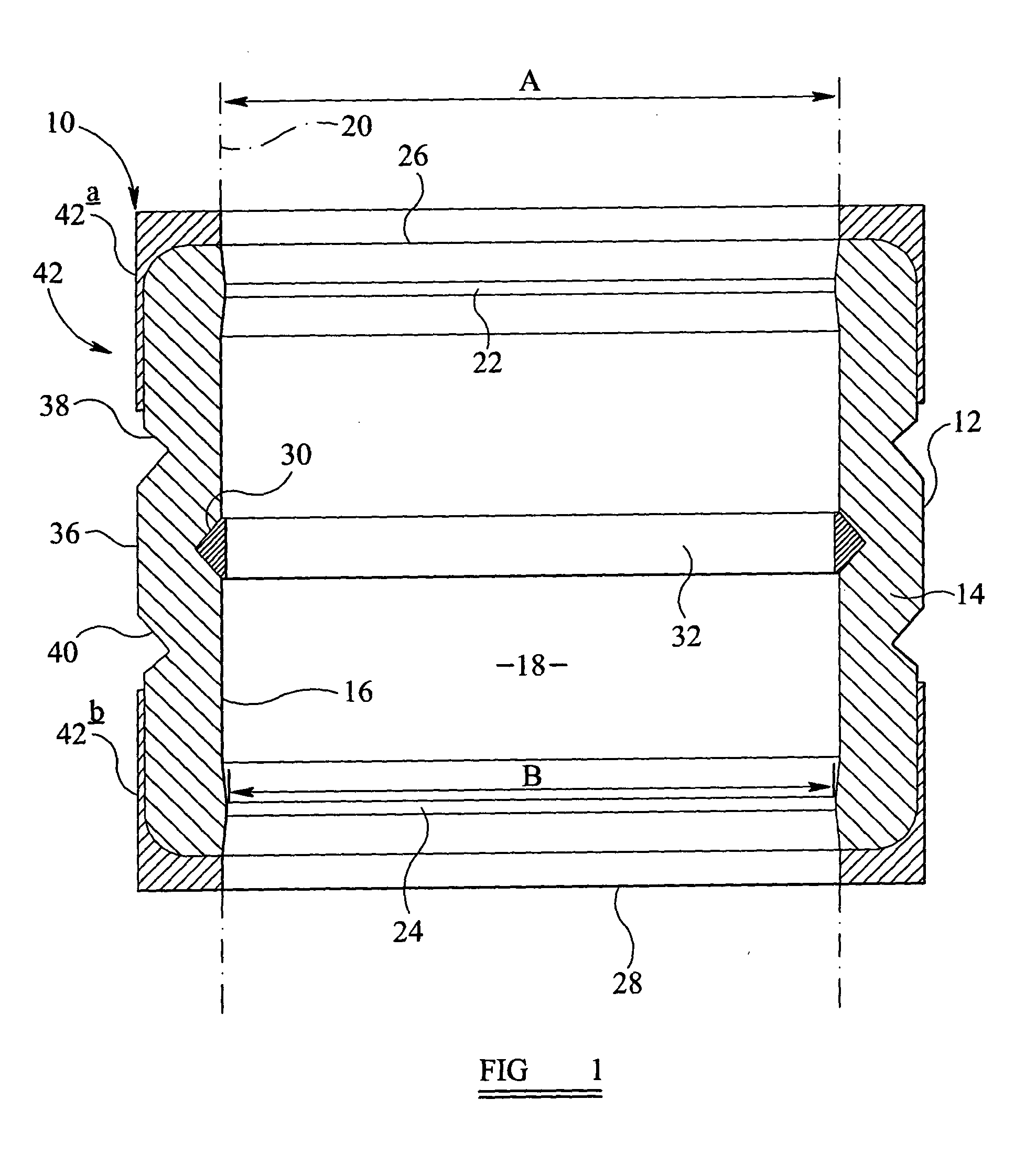
[0057]Reference is firstly made to FIG. 1, a section view of a packer generally indicated by reference numeral 10 incorporating an elastomeric sealing element 12 in accordance with the present invention. The packer 10 is shown in a run-in configuration.

[0058]The sealing element 12 comprises an annular body 14 having an internal surface 16 defining a throughbore 18. The internal surface 16 is adapted to engage a mandrel 20 (shown in broken outline), the mandrel 20 having a mandrel diameter “A”. The internal surface 16 defines first and second tapered ridges 22,24, the throughbore diameter “B” at the ridges 22,24 being less than the mandrel diameter “A”. Provision of the ridges 22,24 provides an interference fit between the ridges 22,24 and the mandrel 20. This ensures no voids are present between the mandrel 20 and the element 12 which gives improved control of the element material, especially at high expansion ratios and gives rise to greater stability when pumping high fluid flow r...

second embodiment

[0067]the present invention will now be described with reference FIGS. 7 to 12. As can be seen from FIG. 7, the packer 60 comprises a much longer sealing element 62 adapted to span a much greater well bore annulus 64 between the packer mandrel 66 and the well bore surface 68. The sealing element is provided with six external surface grooves 70a-f and with five internal surface grooves, 72a-e each incorporating an insert ring 74a-e.

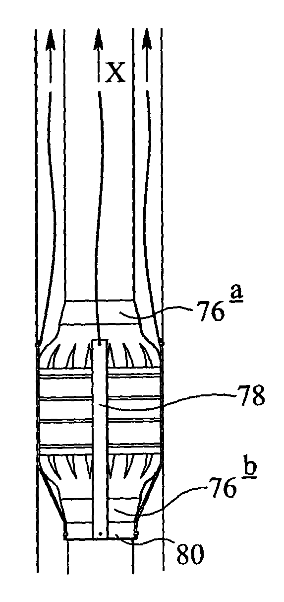
[0068]It will be noted that the inner four external surface grooves 70b-70e are located towards the centre of the sealing element 62 and are distanced from the sealing element back-ups 76a,76b. The sealing element back-ups 76a,76b are, therefore, unable to provide leak paths for the fluid trapped between the inner grooves 70b-e. To facilitate drainage of the inner grooves 70b-e, bleed strips 78 are provided (most clearly seen in FIGS. 10 to 12). The bleed strips 78 are pinned to a bleed strip collar 80 and each bleed strip 78 is connected to the surface b...


PUM


Abstract

A sealing element for a packer is described. The sealing element comprises an annular body having an internal surface defining a throughbore, the internal surface adapted to engage a mandrel having a mandrel diameter. The annular body internal surface defines first and second regions, the throughbore diameter of the regions being less than the mandrel diameter.

Description

FIELD OF THE INVENTION [0001]The present invention relates to an improved packing element for use with a packer.BACKGROUND TO THE INVENTION [0002]Packers are commonly used in the oil and gas industry for sealing an annulus in a well bore. The annulus might exist, for example, between the well bore liner and the production tube.[0003]Each packer generally comprises an elastomeric sealing element which, when axially compressed, expands radially outwards from a mandrel into engagement with, for example, a well bore wall.[0004]There are drawbacks associated with some conventional packers. For example, it is known for the seal between the packing element and the casing to fail if the element has been set in a high temperature environment which subsequently cools. It is also known for the seal to fail when the packer is subject to setting backlash reducing the pressure on the sealing element.[0005]Furthermore, packers “self-set” when there are very high flow rates flowing past an unset pa...

Claims


Application Information

Patent Timeline
IPC IPC(8): E21B33/02
CPCE21B33/1208E21B33/128E21B33/1216
Inventor CLARKE, TIM
Owner RUBBERATKINS
Why Eureka
Try Eureka