Film deposition method

a film deposition and film technology, applied in the field of film deposition methods, can solve the problems of deteriorating damage to the substrate or the film deposition device, and abnormal discharge not only in the film deposition compartment, so as to reduce the quality of the film formed, continuous deposited, and high efficiency

Active Publication Date: 2011-03-17
FUJIFILM CORP
View PDF3 Cites 12 Cited by
  • Summary
  • Abstract
  • Description
  • Claims
  • Application Information

AI Technical Summary

Benefits of technology

[0026]In cases where film deposition is performed on an elongated substrate traveling on a drum in its longitudinal direction as electric power is applied to the drum, the present invention is capable of suppressing abnormal discharge from the drum into the feed and take-up compartment by providing differential compartments between the compartment including the space containing at least one of the position at which the substrate starts to travel on the drum and the position at which the substrate separates from the drum (i.e., wrapping space) and the film deposition compartment and setting the pressure in the wrapping space lower than that of the film deposition compartment. Accordingly, during the film deposition by plasma-enhanced CVD, for example, plasma formation for film deposition is prevented from destabilizing to reduce the quality of the film formed, or damage to the substrate or the film deposition device is also prevented from occurring, thus enabling a high-quality film to be continuously deposited with high efficiency.

Problems solved by technology

However, application of a potential to the drum as in JP 2000-239849 A causes abnormal discharge not only in a film deposition compartment but also in a space where a feed roll or a take-up roll is disposed (hereinafter referred to as “feed and take-up compartment” for the sake of convenience) in particular between the drum and each component such as a guide roller in the feed and take-up compartment.
The abnormal discharge may cause damage to the substrate or the film deposition device, or destabilize the plasma formation for film deposition to deteriorate the quality of the film formed.
However, the earth plate for preventing abnormal discharge cannot be disposed at the position at which the substrate starts to travel on the drum and the position at which the substrate separates from the drum.
Therefore, abnormal discharge from the drum still occurs, which may cause damage to the substrate or the film deposition device, or deteriorate the quality of the film formed.

Method used


Image

  • Film deposition method
  • Film deposition method
  • Film deposition method

Examples


example 1

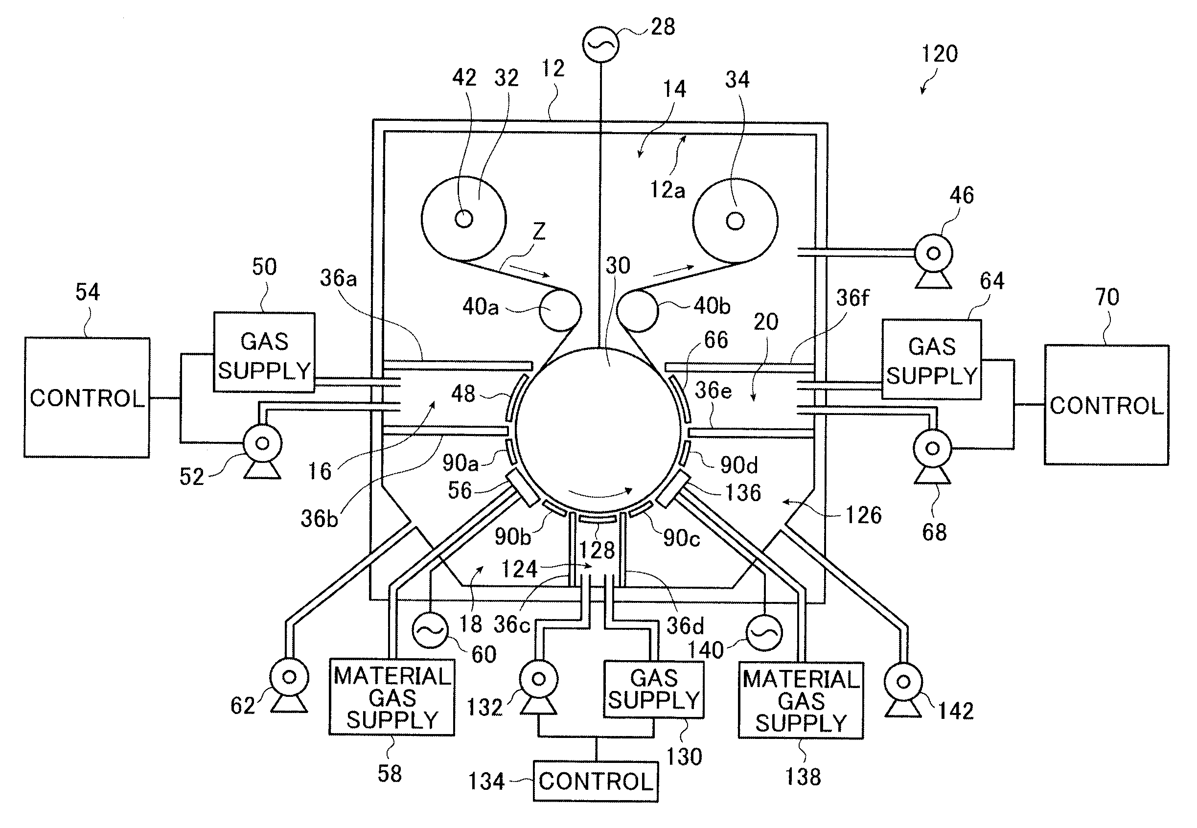
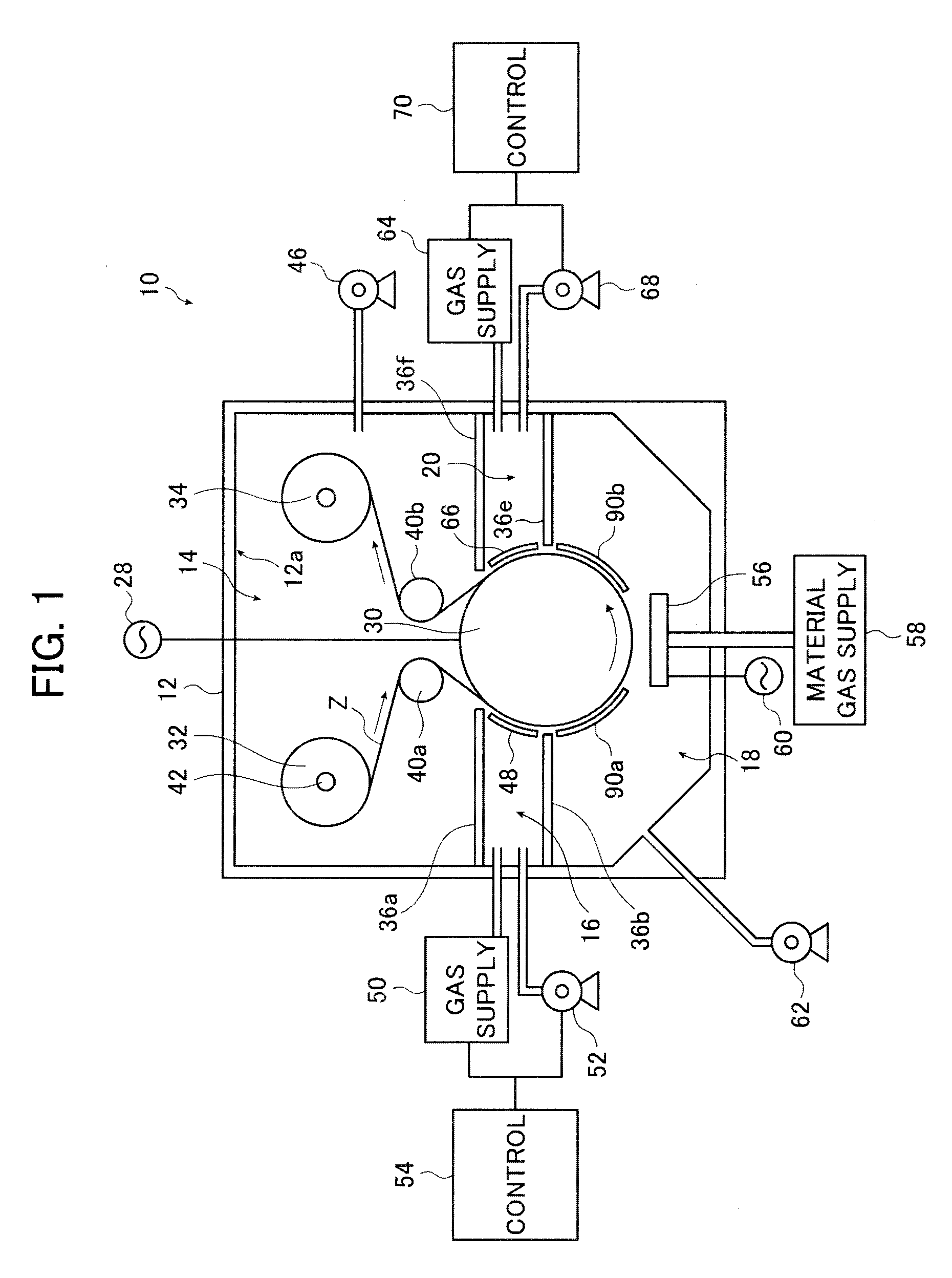
[0166]The film deposition device 10 shown in FIG. 1 was used to deposit a silicon nitride film on a substrate Z.

[0167]The substrate Z used was a PET film (Cosmoshine A4300 available from Toyobo Co., Ltd.).

[0168]Silane gas (at a flow rate of 100 sccm), ammonia gas (at a flow rate of 100 sccm) and nitrogen gas (at a flow rate of 800 sccm) were used as the material gases to form the silicon nitride film by means of CCP-CVD. The gas used to supply to the differential compartments 16 and 20 was nitrogen gas (at a flow rate of 800 sccm).

[0169]The film deposition pressure in the film deposition compartment 18, the pressure in the first differential compartment 16 and the second differential compartment 20, and the pressure in the feed and take-up compartment 14 were set to 50 Pa, 60 Pa and 5 Pa, respectively.

[0170]An RF power source at a frequency of 13.56 MHz was used for the RF power source 60 and the plasma excitation power to be supplied to the shower head electrode 56 was set to 1 kW....


PUM

PropertyMeasurementUnit
pressureaaaaaaaaaa
bias poweraaaaaaaaaa
distanceaaaaaaaaaa

Abstract

A film deposition method deposits a film on a surface of a substrate in strip form traveling on a peripheral surface of a cylindrical drum in at least one film deposition compartment around the peripheral surface of the drum. The method disposes previously a differential compartment between one film deposition compartment and a compartment including a wrapping space containing at least one of a first position at which the substrate starts to travel on the drum and a second position at which the substrate separates from the drum, the differential compartments communicating with the compartment including the wrapping space and the film deposition compartment, sets a first pressure of the wrapping space lower than a second pressure of the at least one film deposition compartment and performs film deposition in the film deposition compartment with electric power supplied to the drum.

Description

BACKGROUND OF THE INVENTION[0001]The present invention relates to a film deposition method suitable to produce functional films.[0002]Various functional films (functional sheets) including gas barrier films, protective films, and optical films such as optical filters and antireflection films are used in various devices including optical devices, display devices such as liquid crystal display devices and organic EL display devices, semiconductor devices, and thin-film solar batteries.[0003]These functional films have been produced by film formation (thin film formation) through vacuum deposition techniques such as sputtering and plasma-enhanced CVD.[0004]Continuous deposition of a film on an elongated substrate is preferred for efficient film formation with high productivity by a vacuum deposition technique.[0005]A typical film deposition device known in the art for conducting such film formation is a roll-to-roll film deposition device using a feed roll having an elongated substrate...

Claims


Application Information

Patent Timeline
Patent Type & Authority Applications(United States)
IPC IPC(8): C23C16/458C23C16/505
CPCC23C16/44C23C16/50C23C16/503C23C16/545C23C16/509C23C16/517C23C16/54C23C16/505C23C16/52
Inventor FUJINAMI, TATSUYATAKAHASHI, SHINSUKEFUJINAWA, JUNTONOHARA, KOUJI
Owner FUJIFILM CORP
Why Eureka
Try Eureka