Connector structure

a technology of connecting structure and connecting flange, which is applied in the direction of coupling base/case, coupling device connection, incorrect coupling prevention, etc., can solve the problems of noise leakage, noise leakage, and the reduction of electromagnetic wave shielding property, etc., to achieve the effect of suppressing the bending of the reinforcing flang

Active Publication Date: 2017-08-08
AUTONETWORKS TECH LTD +2
View PDF12 Cites 2 Cited by
  • Summary
  • Abstract
  • Description
  • Claims
  • Application Information

AI Technical Summary

Benefits of technology

[0013]The metal casing may include a backup ring to be held in contact with the second connector on a side of the second connector opposite to the contact portion. According to this configuration, the backup ring supports the contact portion of the reinforcing flange subjected to a reaction force from the conductive resilient member from a side opposite to the contact portion. By supporting the reinforcing flange, it is possible to suppress the bending of the reinforcing flange by the reaction force from the conductive resilient member and to maintain a contact pressure with the conductive resilient member.

Problems solved by technology

Particularly in devices subject to a lot of vibration such as those mounted in a vehicle, both devices cannot be arranged at a very short distance from each other if the collision of the devices caused by vibration is considered.
Thus, noise may leak out from the above gap between the devices and a reduction of the electromagnetic wave shielding property has become problematic in connectors of a type directly connected to devices.
Further, by sandwiching the conductive resilient member between the metal casings, an error at the time of connector connection caused by a displacement between the metal casings can be absorbed by a resilient force.

Method used


Image

  • Connector structure
  • Connector structure
  • Connector structure

Examples


Embodiment Construction

[0020]A first embodiment is described with reference to FIGS. 1 to 4. A connector structure C for electrically connecting an unillustrated motor and an unillustrated inverter device for driving this motor, for example, in a hybrid vehicle or an electric vehicle is illustrated in this embodiment.

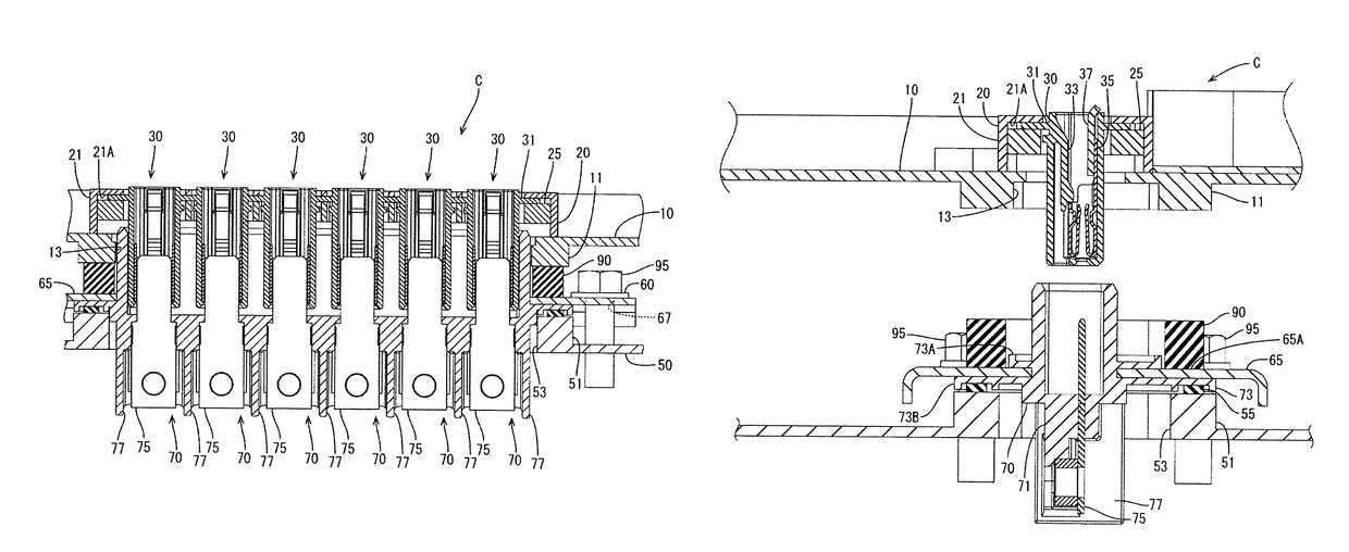
[0021]The connector structure C of this embodiment includes inverter-device-side connectors 30 provided in an inverter case 10, motor-side connectors 70 provided in a motor case 50 and a conductive rubber 90 sandwiched between the inverter case 10 and the motor case 50 as shown in FIGS. 3 and 4.

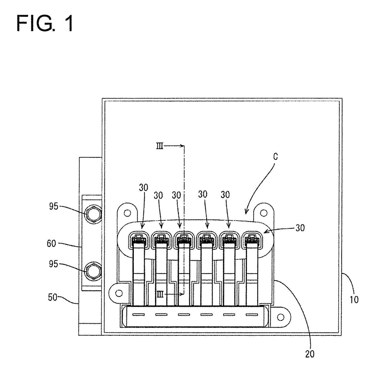
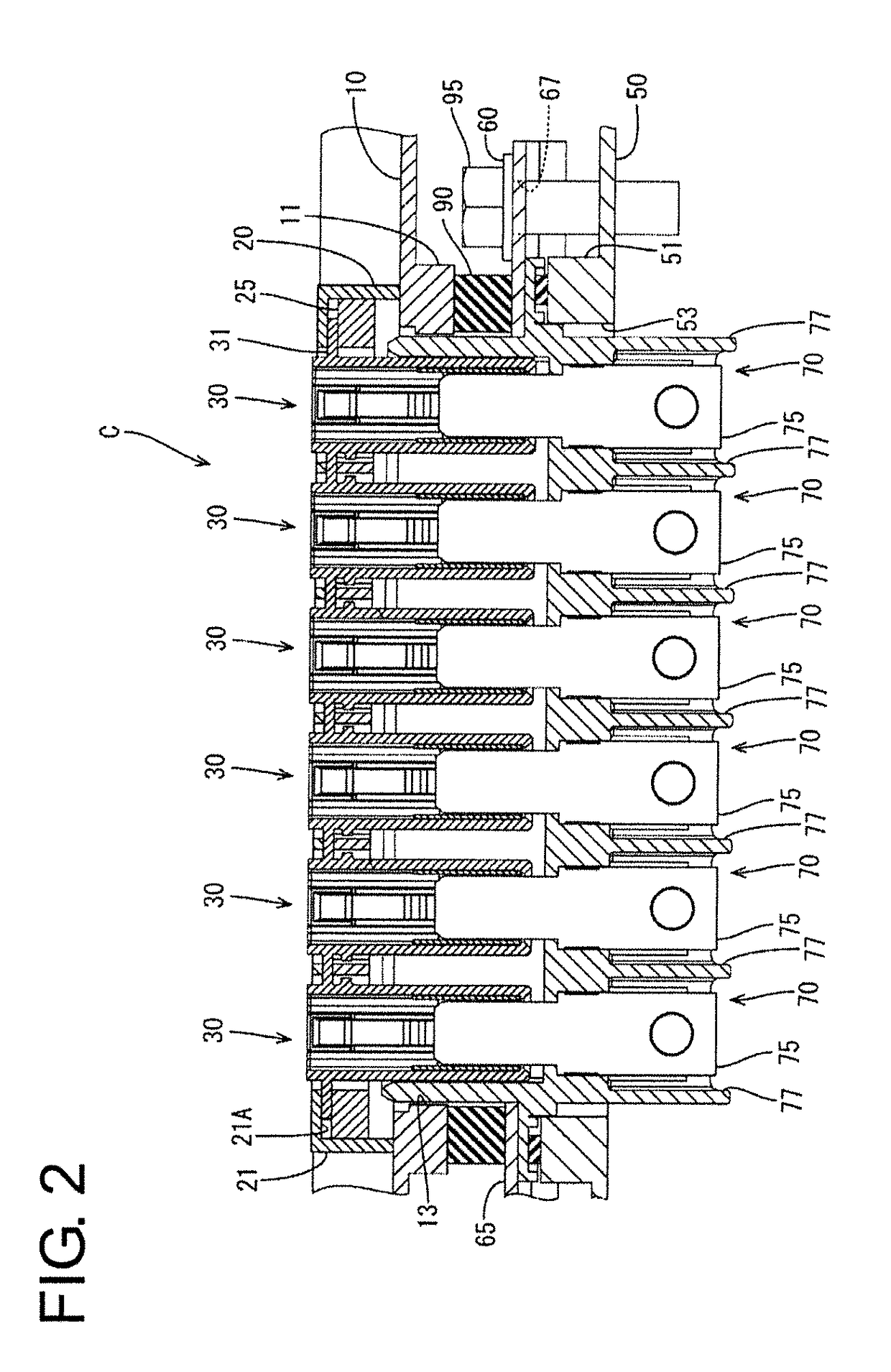
[0022]As shown in FIGS. 1 and 2, six inverter-device-side connectors 30 and six motor-side connectors 70 are arranged in parallel along a direction perpendicular to a connecting direction of the inverter-device-side connectors 30 and the motor-side connectors 70 between the inverter device and the motor to electrically connect the inverter device and the motor. The six inverter-device-side connectors 3...


PUM


Abstract

A connector structure (C) for connecting a plurality of electric devices accommodated in metal casings (10, 50) and arranged proximate to each other includes a first connector (30) provided in one (10) of the metal casings, a second connector (70) provided in the other (50) of the metal casings and configured to electrically connect the electric devices by being connected to the first connector (30), and a conductive resilient member (90) arranged to be sandwiched between the both metal casings while being electrically conductive to the metal casings (10, 50) and surround connected parts of the first and second connectors (30, 70).

Description

BACKGROUND[0001]1. Field of the Invention[0002]The present invention relates to a connector structure.[0003]2. Description of the Related Art[0004]In electric vehicles and hybrid vehicles, a travel motor and an inverter device for driving this travel motor often are connected by a wiring harness having an electromagnetic wave shielding function. However, in recent years, it has been considered to connect an inverter device and a motor by direct-connection type connectors without using a wiring harness, for example, as described in Japanese Unexamined Patent Publication No. 2007-280913) for the miniaturization and weight reduction of a device configuration.[0005]A configuration in which the inverter device (power converter) and the motor (electric motor) are accommodated respectively in individual metal casings and a male connector and a female connector to be connected to each other are fixed to the respective metal casings is disclosed in the above publication. The two connectors c...

Claims


Application Information

Patent Timeline
Patent Type & Authority Patents(United States)
IPC IPC(8): H01R13/64H01R13/6584H01R13/52
CPCH01R13/6584H01R13/5219H01R13/2414
Inventor MUKUNO, JUNICHITAKATA, KENSAKU
Owner AUTONETWORKS TECH LTD
Why Eureka
Try Eureka