Optical Component and Wear Sensor

Inactive Publication Date: 2011-02-17
BRIAN INVESTMENTS
View PDF12 Cites 13 Cited by
  • Summary
  • Abstract
  • Description
  • Claims
  • Application Information

AI Technical Summary

Benefits of technology

[0019]In an embodiment the reflective portion is formed of one or more reflective elements which are ablated as the wearable portion is worn, such that ablation of the one or more reflective elements reduces the amount of reflection of the reflective portion.

Problems solved by technology

Difficulties arise when monitoring and determining the extent of wear of the wear plates because, for example, the plates are located in positions that are difficult to access.
As a consequence, it is difficult to determine the exact timing of a wear plate change-out because it is desirable to use the wear plate to the maximum extent of its life, but not to the extent of failure.
It is often impossible to determine the extent of wear to some components prior to component failure or disassembly / inspection during a shutdown.

Method used


Image

  • Optical Component and Wear Sensor
  • Optical Component and Wear Sensor
  • Optical Component and Wear Sensor

Examples


Embodiment Construction

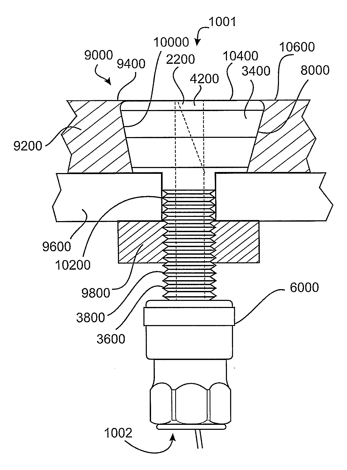
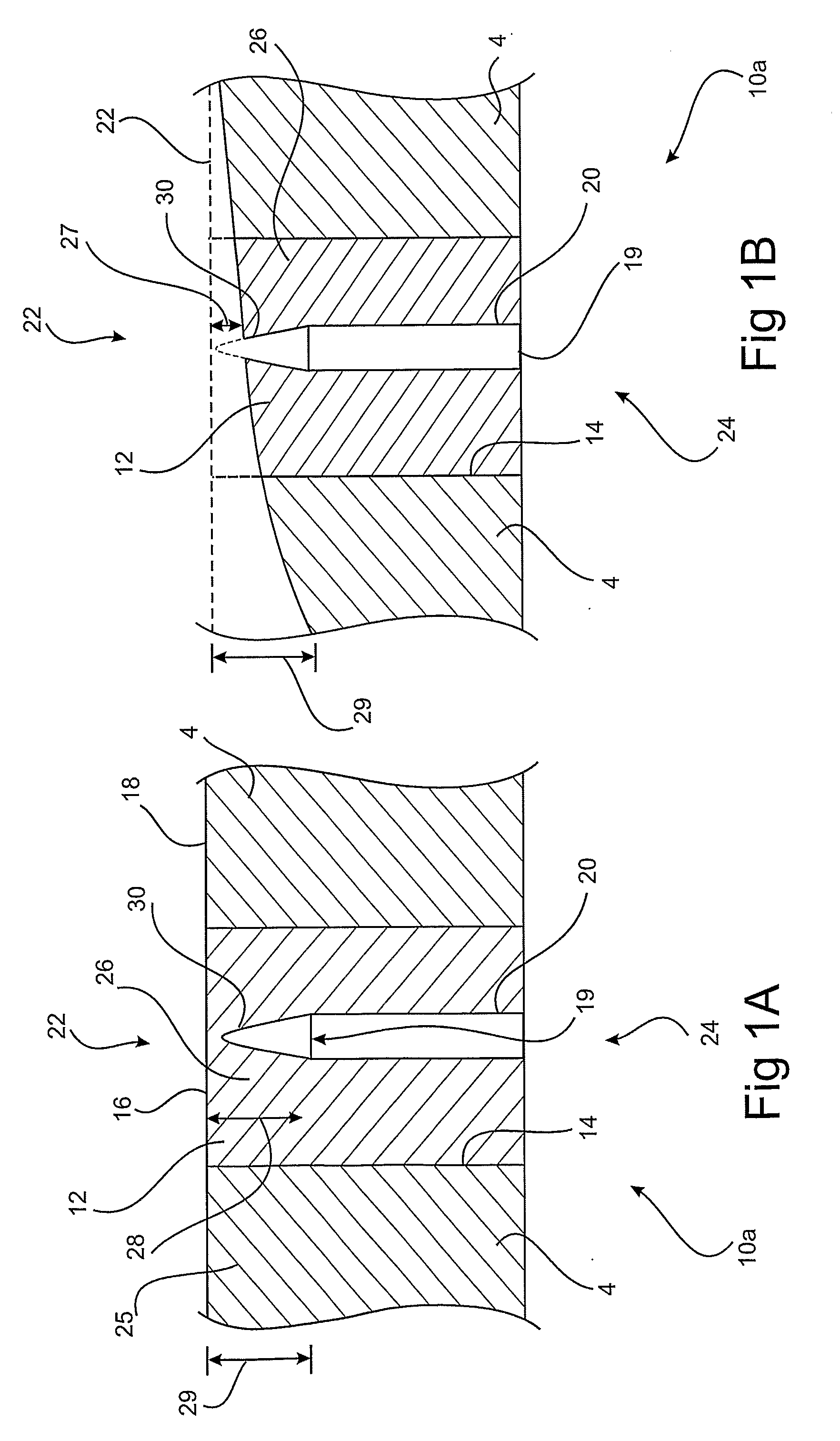
[0134]The present invention relates generally to an optical component and a wear measuring device. The optical component has particular application in some embodiments of the device, however it is not intended to be exclusively used in the device and may find other applications. The device comprises a body having a wearable portion at a first end, a light conductive region internal to the body and the light conductive region has a reflective portion within the wearable portion. The reflective portion is configured to reflect light directed through the light conductive portion and at the reflective portion back down the light conductive portion. One or more characteristics of light reflected by the reflective portion are related to the extent of wear to the wearable portion. Further embodiments are described below.

[0135]The optical component comprises a longitudinal axis and a plurality of reflective elements spaced along said longitudinal axis. The reflective elements are arranged t...


PUM


Abstract

A wear measuring device comprises a body having a wearable portion at the first end, a light conductive region internal to the body and the light conductive region has a reflective portion within the wearable portion. The reflective portion is configured to reflect light directed through the light conductive portion and at the reflective portion back down the light conductive portion. One or more characteristics of light reflected by the reflective portion are related to the extent of wear to the wearable portion. An optical component comprises a longitudinal axis and a plurality of reflective elements spaced along said longitudinal axis. The reflective elements are arranged to reflect light directed in a direction substantially aligned with said longitudinal axis. The magnitude of the reflectance is a function of physical degradation, ablation or wear of the component in a direction along the length of the component.

Description

FIELD OF THE INVENTION[0001]The present invention relates to an optical component and a wear sensor. The optical component can non-exclusively be used in a device for measuring wear. Particularly, though not exclusively, the device is for measuring in-situ wear on a wear plate.BACKGROUND OF THE INVENTION[0002]Plates of hardened material are often used to minimise the effect of wear on structural elements of a piece of equipment. The material of the wear plate is selected for resistance to wear. The wear plates act as a sacrificial element so that plates are worn rather than the structural element of the equipment.[0003]Difficulties arise when monitoring and determining the extent of wear of the wear plates because, for example, the plates are located in positions that are difficult to access. As a consequence, it is difficult to determine the exact timing of a wear plate change-out because it is desirable to use the wear plate to the maximum extent of its life, but not to the extent...

Claims


Application Information

Patent Timeline
IPC IPC(8): G01N21/55
CPCG01M11/08G01B11/24
Inventor DAVIES, BRIAN
Owner BRIAN INVESTMENTS
Why Eureka
Try Eureka