
Optical transmission and receiving device for implementing passive alignment of components and method for passively aligning components

a technology passive alignment, which is applied in the field of optical transmission and receiving device for implementing passive alignment of components and passive alignment of components, can solve the problems of difficult use time-consuming manufacturing process, and high cost of optical alignment device, so as to reduce the amount of reflection loss

Active Publication Date: 2015-12-31
CELLCUBES CO LTD
View PDF24 Cites 2 Cited by
  • Summary
  • Abstract
  • Description
  • Claims
  • Application Information

AI Technical Summary

Benefits of technology

This solution simplifies the alignment process, reduces costs, and ensures accurate alignment without the need for complex equipment, facilitating mass production of bi-directional optical devices for improved data communication speeds at lower costs.

Problems solved by technology

In conventional methods of signal transmission based on fiber optics, however, the optical device for coupling the light-emitting elements with the optical fiber or for coupling the light emitted from the optical fiber with the light-receiving elements is not only very expensive but also quite difficult to use in performing optical alignment.
This method of active optical alignment, in which the light-emitting element or light-receiving element is driven directly and the degree of alignment with the optical fiber is sensed in real time to yield the optimum degree of alignment, requires a time-consuming manufacture process and expensive assembly apparatus.

Method used


Image

  • Optical transmission and receiving device for implementing passive alignment of components and method for passively aligning components
  • Optical transmission and receiving device for implementing passive alignment of components and method for passively aligning components
  • Optical transmission and receiving device for implementing passive alignment of components and method for passively aligning components

Examples


Embodiment Construction

[0051]Specific embodiments of the present invention are described below with reference to the accompanying drawings.

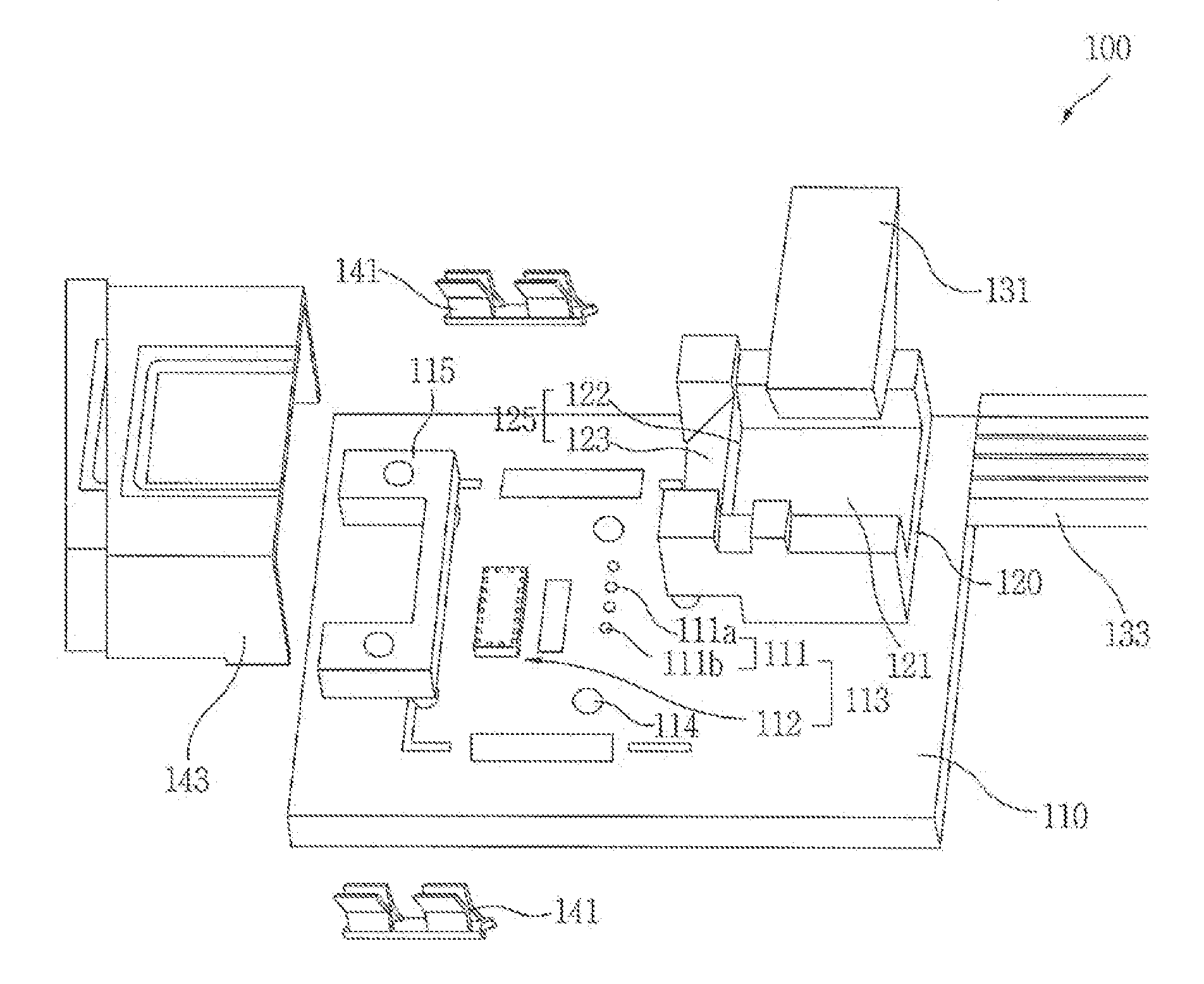
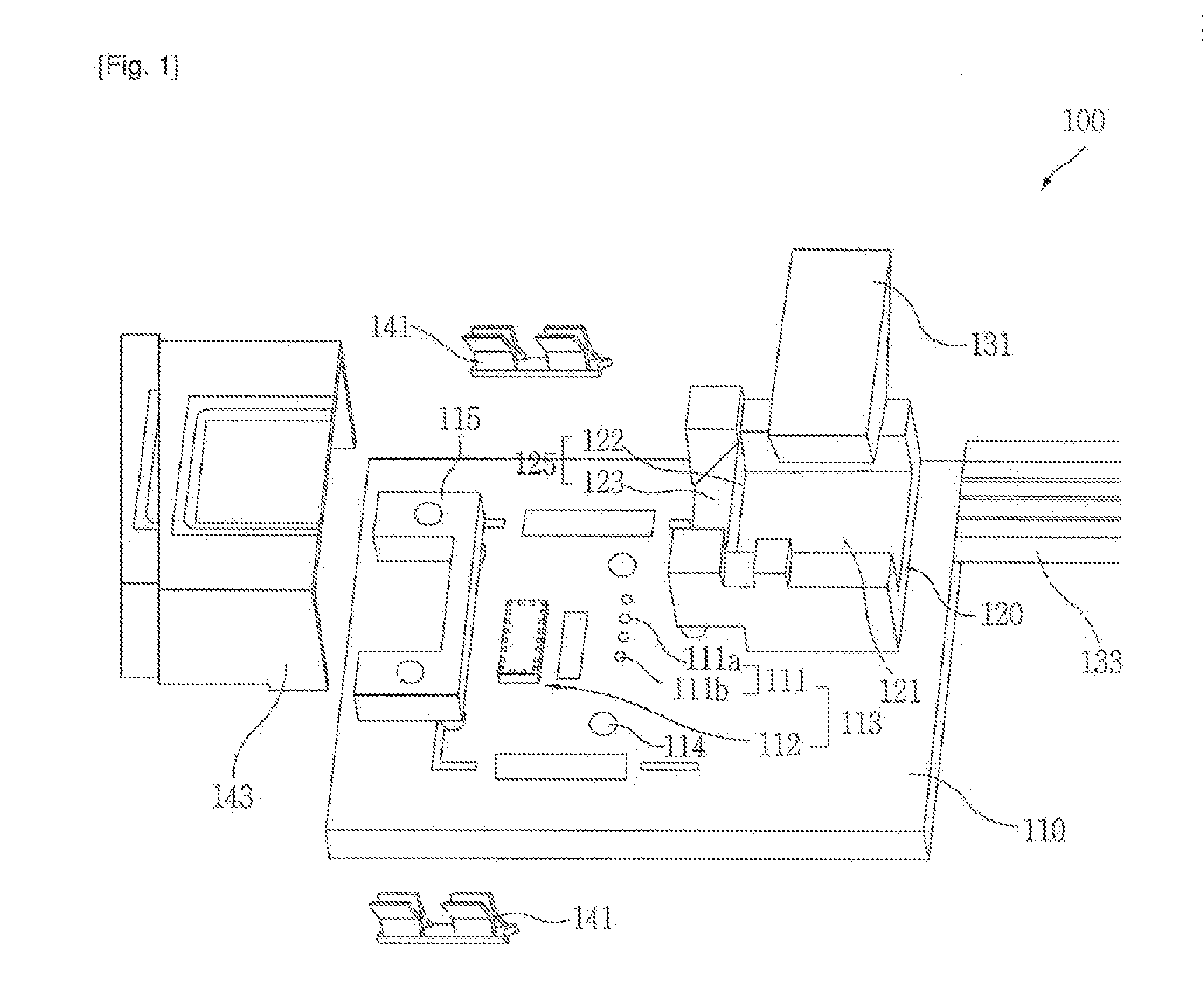
[0052]FIG. 1 illustrates the constitution of an optical device according to the present invention.

[0053]Referring to FIG. 1, an optical device 100 of the present invention includes a substrate 110, an optical element part 111 that includes light-emitting elements 111a and light-receiving elements 111b, a driver circuit 112, a photoelectric converter part 113 that includes the optical element part and the driver circuit 112, substrate holes 114, an alignment reference part 115 arranged on the substrate 110 for passively aligning the optical element part 111 and the lens-optical fiber connection part 120, a lens-optical fiber connection part 120 for collecting light, altering the optical path, and securing and aligning the optical fiber 133, an optical fiber pin 131 connected to one end of the lens-optical fiber connection part 120, an optical fiber 133 for implementing ...


PUM


Abstract

An optical device for implementing passive alignment of parts and a method therefor, more particularly an optical device and a method therefor that utilize an alignment reference part arranged on the substrate to passively align an optical element part with a lens-optical fiber connection part. For the passive alignment of parts, connection pillars of an alignment reference part are coupled to substrate holes, one or more light-emitting elements and one or more light-receiving elements are aligned in a row in a particular interval with respect to alignment holes arranged opposite each other in the alignment reference part, a lens-optical fiber connection part is aligned with respect to the alignment holes, and an optical fiber is aligned with the optical alignment point at a surface of a prism forming a portion of the lens-optical fiber connection part.

Description

CROSS-REFERENCE TO RELATED APPLICATIONS[0001]This application is a division of U.S. patent application Ser. No. 13 / 512,478, entitled “OPTICAL TRANSMISSION AND RECEIVING DEVICE FOR IMPLEMENTING PASSIVE ALIGNMENT OF COMPONENTS AND METHOD FOR PASSIVELY ALIGNING COMPONENTS,” filed Feb. 6, 2013, which is a United States National Stage application under 35 U.S.C. §371 of International Patent Application No. PCT / KR2011 / 006902, filed Sep. 19, 2011, entitled the same, which claims the benefit to Korean Patent Application No. 10-2010-0091614, filed Sep. 17, 2010, each of which is incorporated by reference into this application as if fully set forth herein.TECHNICAL FIELD[0002]The present invention relates to an optical device for implementing passive alignment of parts and a method therefor, more particularly to an optical device and a method therefor that utilize an alignment reference part arranged on the substrate to passively align an optical element part with a lens-optical fiber connect...

Claims


Application Information

Patent Timeline
Patent Type & Authority Applications(United States)
IPC IPC(8): G02B6/42G02B6/32G02B6/34
CPCG02B6/4214G02B6/425G02B6/4243G02B6/4244G02B6/4245G02B6/4249G02B6/4277G02B6/26G02B6/32G02B6/34Y10T29/49895G02B6/4257G02B6/424G02B6/4239G02B6/4231G02B6/4206G02B6/423
Inventor SON, YUNG SUNGLEE, SANG-SHINLEE, HAK-SOONPARK, JUN-YOUNG
Owner CELLCUBES CO LTD
Learn More