Wireless terminal and retransmission method

a technology of retransmission and wireless terminals, applied in the direction of transmission monitoring, instruments, sustainable buildings, etc., can solve the problems of inability to receive frames, wlans are likely to be subject to noise and interference influence, and transmission errors are frequent, so as to reduce power consumption of access points and stations, the effect of improving communication quality

Inactive Publication Date: 2011-02-17
PANASONIC CORP
View PDF5 Cites 16 Cited by
  • Summary
  • Abstract
  • Description
  • Claims
  • Application Information

AI Technical Summary

Benefits of technology

[0017]According to the present invention, by setting the upper limit value of the number of retransmissions lower in the case where there are interference waves equal to or above a predetermined level in a WEAN than where there are interference waves below the predetermined level, it is possible to secure the number of stations that can perform speech communication with an access point in a WLAN at the same time, improve communication quality and reduce the power consumption of the access point and stations.

Problems solved by technology

A WLAN uses an ISM (Industrial, Scientific and Medical) band, which needs not be licensed, and therefore transmission error frequently occurs.
Even if narrowband transmission is performed, the WLAN is likely to be subject to the influence of noise and interference.
Also, if a terminal enters a dead point due to multipath fading in addition to noise, it is not possible to receive frames.
That is, if the transmitting source of data frames does not receive ACK's, the frames are decided to be lost.
Transmission error has to be detected in the transmitting station.

Method used


Image

  • Wireless terminal and retransmission method
  • Wireless terminal and retransmission method
  • Wireless terminal and retransmission method

Examples


Embodiment Construction

[0023]Now, embodiments of the present invention will be explained in detail with reference to the accompanying drawings.

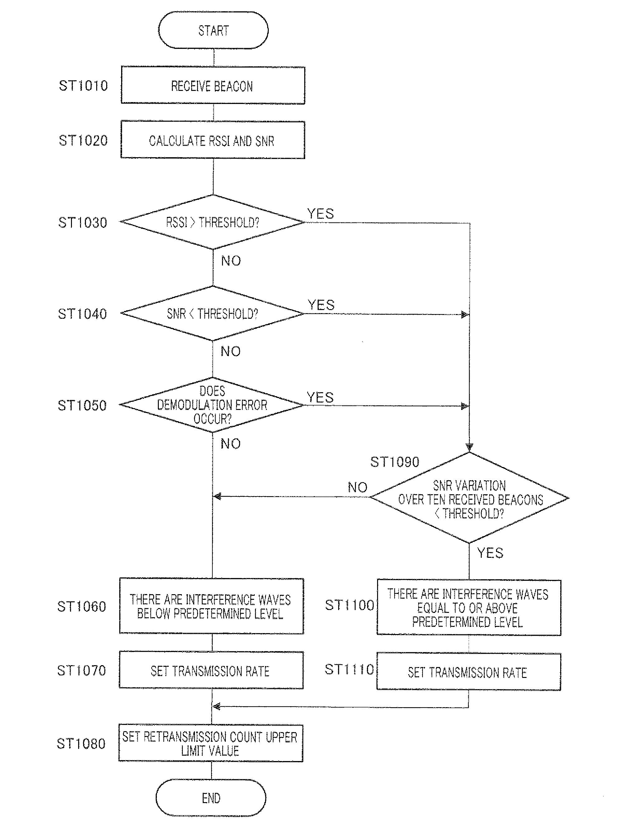
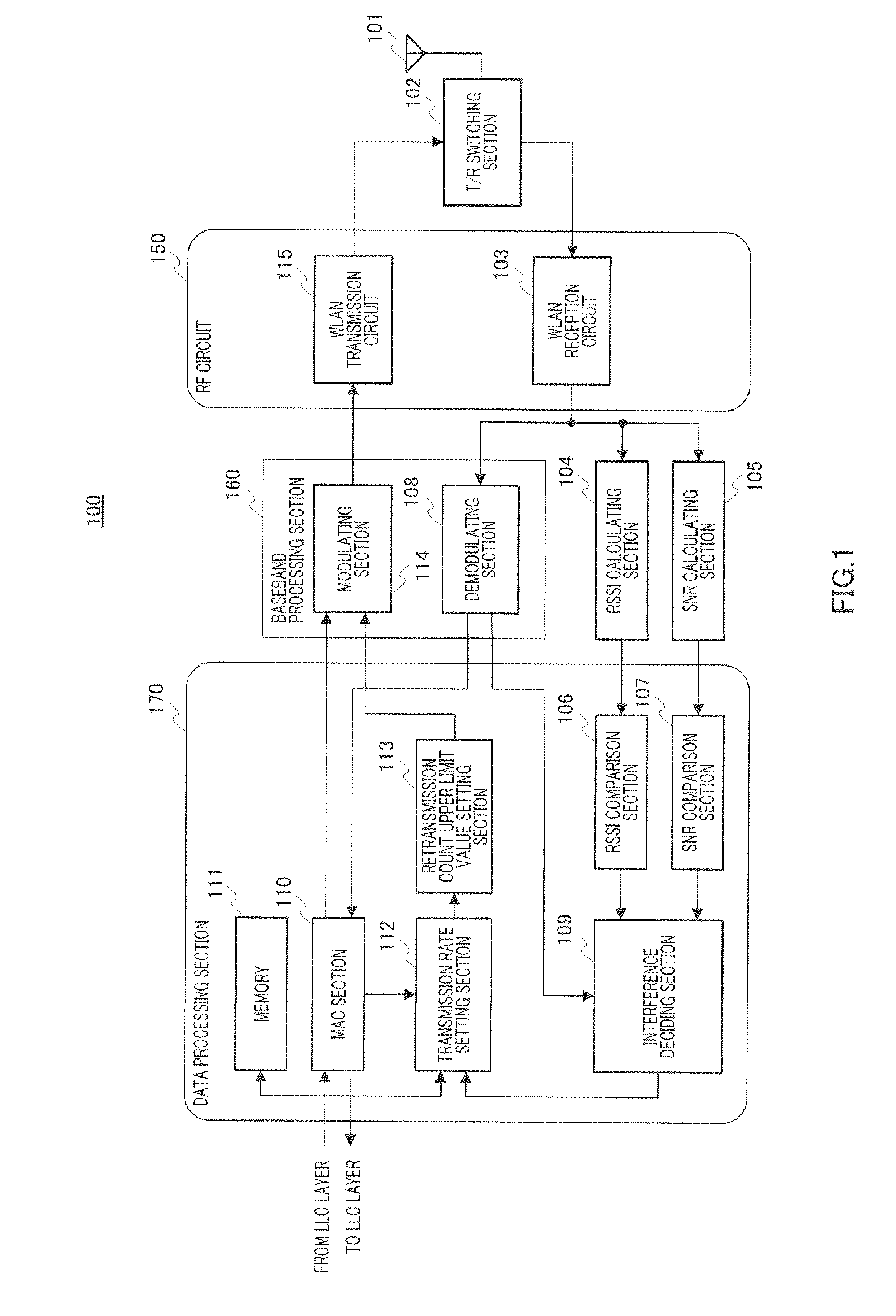
[0024]FIG. 1 is a block diagram showing the configuration of radio terminal apparatus (or station) 100 according to an embodiment of the present invention. Here, in FIG. 1, the configuration and operations related to the setting of retransmission count upper limit values, will be mainly explained.

[0025]In FIG. 1, radio terminal apparatus 100 is mainly provided with antenna 101, T / R (transmission / reception) switching section 102, WLAN reception circuit 103, RSSI (Received Signal Strength Indicator) calculating section 104, SNR (Signal to Noise Ratio) calculating section 105, RSSI comparison section 106, SNR comparison section 107, demodulating section 108, interference deciding section 109, MAC (Medium Access Control) section 110, memory 111, transmission rate setting section 112, retransmission count upper limit value setting section 113, modulating section 114 and...


PUM


Abstract

A wireless terminal capable of securing the number of station units capable of simultaneous communication with one unit of access point, reducing power consumption, and ensuring stable communication quality. In the wireless terminal (100), an interference determining section (109) determines whether or not an interference wave is at a predetermined level or more on the basis of the RSSI and SNR of the received signals which are calculated by an RSSI (Received Signal Strength Indicator) calculating section (104) and SNR (Signal to Noise Ratio) calculating section (105) and the presence/absence of a demodulation error notified from a demodulation section (108). A number-of-retransmission upper limit setting section (113) sets the upper limit of the number of retransmission smaller than when the interference wave is at the predetermined level or lower if the interference wave is at the predetermined level or more. A WLAN transmitting circuit (115) repeats the transmission of a transmitting signal by the upper limit number of retransmission till the transmission of the transmitting signal is successful.

Description

TECHNICAL FIELD[0001]The present invention relates to a wireless terminal apparatus and retransmission method used in a wireless local area network (“WLAN”).BACKGROUND ART[0002]At present, a transmission speed of 11 Mbps in IEEE 802.11b and a maximum transmission speed of 54 Mbps in IEEE 802.11a and IEEE 802.11g are defined for a wireless LAN (“WLAN”), and its supporting products are marketed. This allows a low-cost WLAN to become popular and increases the number of users to build a WLAN, thereby sharply increasing the popularity of a WLAN. Nowadays, a WLAN is used not only by companies for their services, but also by individual users for their home networks.[0003]As a basic use method of a WLAN, there are two types of the infrastructure mode and ad hoc mode. With the former infrastructure mode, a WLAN connects by radio between an access point corresponding to a radio base station for portable telephones and a terminal (or station). With the latter ad hoc mode, a WLAN directly inter...

Claims


Application Information

Patent Timeline
Patent Type & Authority Applications(United States)
IPC IPC(8): H04B17/00
CPCH04L1/0002Y02B60/50H04L1/1887H04L1/0034
Inventor SATO, MITSURU
Owner PANASONIC CORP
Why Eureka
Try Eureka