
Load balancing for packet switched alarm monitoring

a packet switching and alarm monitoring technology, applied in the field of security systems, can solve problems such as cumbersome manual intervention, error-prone, and inability to meet the needs of users, and achieve the effect of reducing the number of alarms

Active Publication Date: 2011-02-17
JOHNSON CONTROLS TYCO IP HLDG LLP
View PDF6 Cites 173 Cited by
  • Summary
  • Abstract
  • Description
  • Claims
  • Application Information

AI Technical Summary

Benefits of technology

[0009]Exemplary of an embodiment of the invention, alarm panels are assigned to monitoring servers at a monitoring station by an allocation server. Each panel obtains the data network address of its assigned monitoring server by contacting the allocation server, upon installation / configuration. The provided data network address is stored at the panel for later use. This allows the allocation server to fairly and flexibly distribute monitoring responsibility for the many panels across multiple monitoring servers.

Problems solved by technology

Such manual intervention, however, is cumbersome and may be error prone.

Method used


Image

  • Load balancing for packet switched alarm monitoring
  • Load balancing for packet switched alarm monitoring
  • Load balancing for packet switched alarm monitoring

Examples


Embodiment Construction

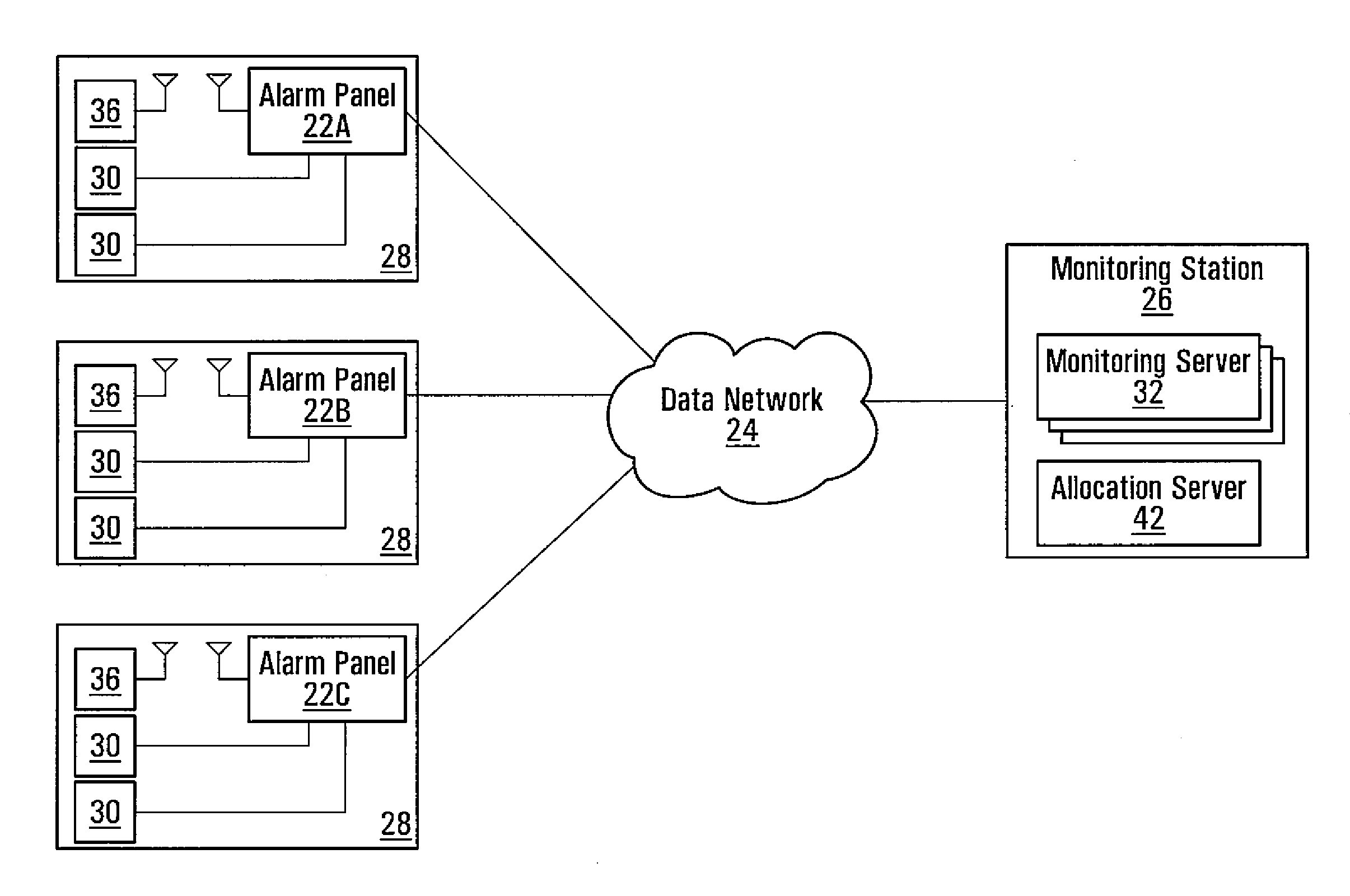
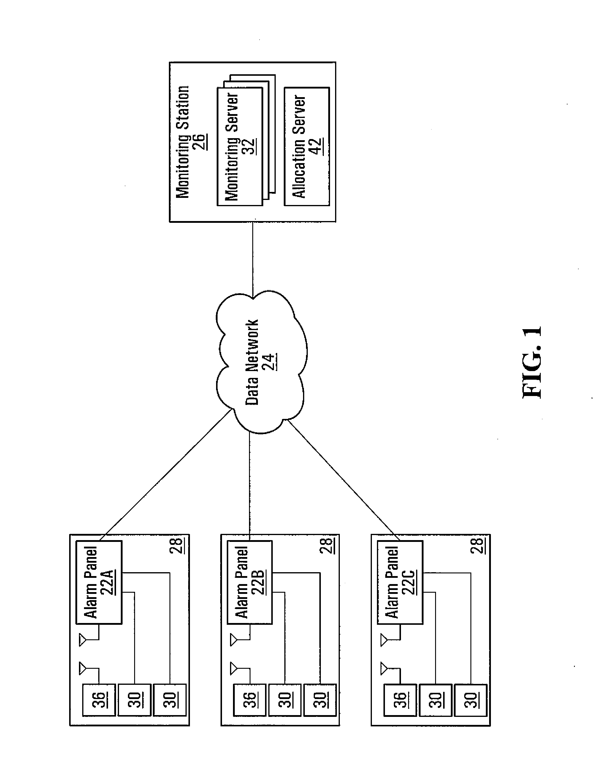
[0018]FIG. 1 depicts an exemplary security system infrastructure 20 of security systems including multiple alarm panels 22a, 22b, 22c (individually and collectively panel 22) at customer premises 28a, 28b, 28c (individually and collectively premises 28), respectively, communicating through a data network 24 such as the Internet, with a central monitoring station 26. As will be appreciated, data network 24 may be any combination of wired and wireless links capable of carrying packet switched traffic, and may span multiple carriers, and a wide geography. In one embodiment, data network 24 may simply be the public Internet. Further access points, such as DSL modems, wireless radios, and the like possibly interconnecting panels 22 with data network 24 are not illustrated. Interconnected devices, such as network interface case (NICs) are assigned source data network addresses dynamically using known-networking protocols (e.g. DHCP), or statically.

[0019]At residential or business premises...


PUM


Abstract

Alarm panels are assigned to monitoring servers at a monitoring station by an allocation server. Each panel obtains the data network address of its assigned monitoring server by contacting the allocation server, upon installation / configuration. The provided data network address is stored at the panel for later use. This allows the allocation server to fairly and flexibly distribute monitoring responsibility for the many panels across multiple monitoring servers.

Description

CROSS-REFERENCE TO RELATED APPLICATIONS[0001]This application claims benefits from U.S. Provisional Patent Application No. 61 / 232,849 filed Aug. 11, 2009, the contents of which are hereby incorporated herein by reference.FIELD OF THE INVENTION[0002]The present invention relates generally to security systems, and more particularly to methods and devices for load balancing of alarm monitoring facilities.BACKGROUND OF THE INVENTION[0003]It is common for businesses and homeowners to have a security system for detecting alarm conditions at their premises and reporting these to a monitoring station. One of the primary functions of the monitoring station is to notify a human operator when one or more alarm conditions have been sensed by detectors installed at a monitored premise.[0004]Detectors may vary from relatively simple hard-wired detectors, such as door or window contacts to more sophisticated battery operated ones such as motion and glass break detectors. The detectors may all repo...

Claims


Application Information

Patent Timeline
Patent Type & Authority Applications(United States)
IPC IPC(8): G06F15/16
CPCB60R25/10H04L29/12066H04L61/157H04L41/0893H04L61/1511H04L29/1216H04L61/4557H04L61/4511G08B25/003
Inventor FOISY, STEPHANE
Owner JOHNSON CONTROLS TYCO IP HLDG LLP
Learn More