High-efficiency, high current solar cell and solar module

a solar cell and high-current technology, applied in the field of optoelectronic devices, can solve the problems of premature failure of solder joints, incompatibility between solder and silicon wafer materials, and individual optoelectronic devices producing only a relatively small voltage, etc., to increase the number of electrical connections, increase the number of backside conductor ampacity, and increase the cell size

Inactive Publication Date: 2011-02-24
SHEATS JAMES R
View PDF0 Cites 55 Cited by
  • Summary
  • Abstract
  • Description
  • Claims
  • Application Information

AI Technical Summary

Benefits of technology

The present invention provides methods for producing high-current photovoltaic cells that have increased power output while maintaining flexibility and durability. These methods involve improving cell design and optimizing material properties such as reducing the amount of opaque conductive materials on the front surface of the cells (which can block sunlight) and increasing the number of electrical connections between different parts of the cells. Additionally, these methods allow for larger cells to be made that still achieve efficient energy conversion. Overall, this technology allows for higher performance solar modules that may better meet the needs of various applications including renewable electricity production.

Problems solved by technology

The technical problem addressed in this patent text is to develop a cost-effective alternative to conventional solar cells that can connect to the grid and reduce resistive losses, while also allowing for individual cell yield optimization. The current manufacturing process is slow and expensive, and vacuum deposition is difficult to implement in large-scale production. The invention aims to overcome these challenges by developing a new method for manufacturing solar cells that is cost-effective and can be done on flexible substrates.

Method used


Image

  • High-efficiency, high current solar cell and solar module
  • High-efficiency, high current solar cell and solar module
  • High-efficiency, high current solar cell and solar module

Examples


Embodiment Construction

b>FIGS. 15A-15C show a method for forming an insulating layer according to embodiments of the present invention.

[0041]FIGS. 16A-16B show a method for forming an insulating layer according to embodiments of the present invention.

[0042]FIGS. 16A-16B show a method for forming an insulating layer according to embodiments of the present invention.

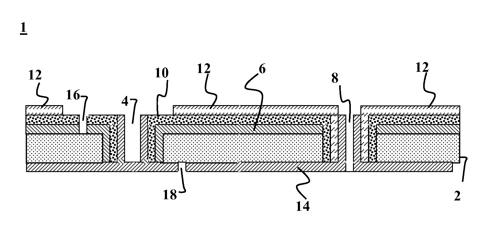
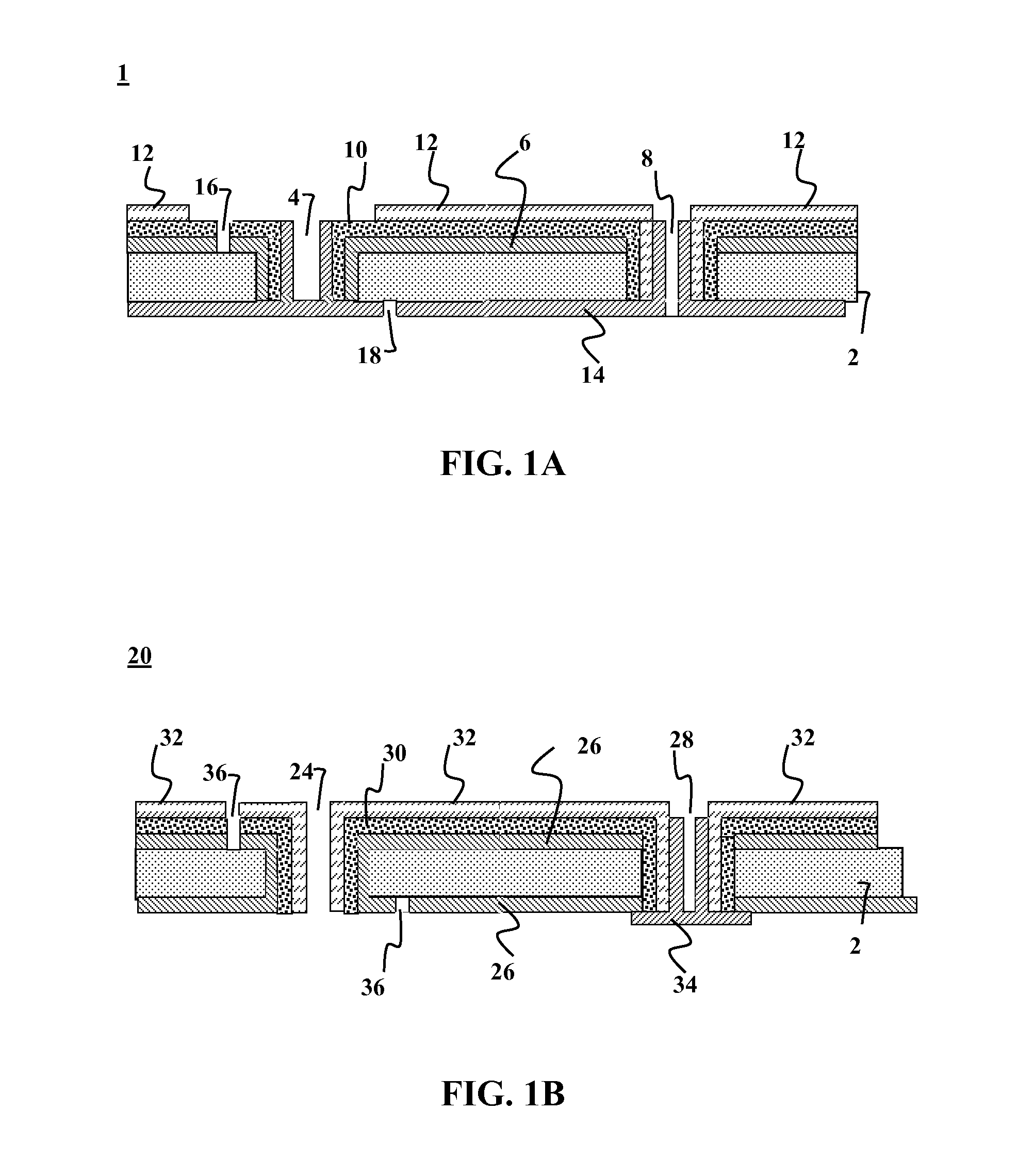
[0043]FIGS. 17 and 18 show cross-sectional views of solar cells according to embodiments of the present invention.

[0044]FIGS. 19 and 20 show top down views of solar cells according to embodiments of the present invention.

[0045]FIGS. 21 and 22 show top down views of solar modules according to embodiments of the present invention.

[0046]FIGS. 23 and 24 show views of systems according to embodiments of the present invention.

[0047]FIGS. 25 and 26 show cross-sectional views of solar cells according to embodiments of the present invention.

[0048]FIGS. 27 through 29 show side views of strain relief elements according to embodiments of the present inventi...


PUM


Abstract

Methods and devices are provided for high-efficiency solar cells. In one embodiment, a high current photovoltaic apparatus is provided comprising of a thin-film absorber layer solar module of arbitrary size having an electrical output with a current of greater than about 2 amperes when the module is under AM1.5G illumination at 25° C. Optionally, the current is at least about 5 amperes. Optionally, the current is at least about 15 amperes. Optionally, the current is at least about 50 amperes. Optionally, the current is at least about 100 amperes.

Description


Claims


Application Information

Patent Timeline
Owner SHEATS JAMES R
Why Eureka
Try Eureka