Support assembly

a technology of supporting parts and components, applied in the direction of mechanical equipment, transportation and packaging, fuselages, etc., can solve the problems of increasing friction and wear rate, increasing wear rate,

Active Publication Date: 2011-02-24
AIRBUS OPERATIONS LTD
View PDF8 Cites 36 Cited by
  • Summary
  • Abstract
  • Description
  • Claims
  • Application Information

AI Technical Summary

Benefits of technology

[0009]According to the present invention, there is provided support assembly for guiding a flap on an aircraft wing during deployment of the flap, the assembly comprising a guide track defining a two-dimensional path, a cylindrical bearing follower having a longitudinal axis constrained so as to follow said path during flap deployment, a shaft extending from the bearing follower and, a spherical bearing coupling an end of the shaft to the bearing follower such that the bearing follower is rotatable relative to the shaft about the longitudinal axis of the bearing follower as it travels along the track, the spherical bearing also enabling angular rotation of the shaft about a centre of the spherical bearing, such that a flap supported by said assembly is free to move in multiple directions.

Problems solved by technology

In the preferred embodiment, the bearing follower and guide track are sized so that the bearing follower is free to roll along the track during deployment, thereby minimising skidding or scrubbing of the follower across the surface of the guide track, which would result in increased wear rates.
However it will be appreciated that without any clearance between the bearing housing and the other side wall, the housing would rub against that other side wall increasing friction and wear rates.

Method used


Image

  • Support assembly
  • Support assembly
  • Support assembly

Examples


Embodiment Construction

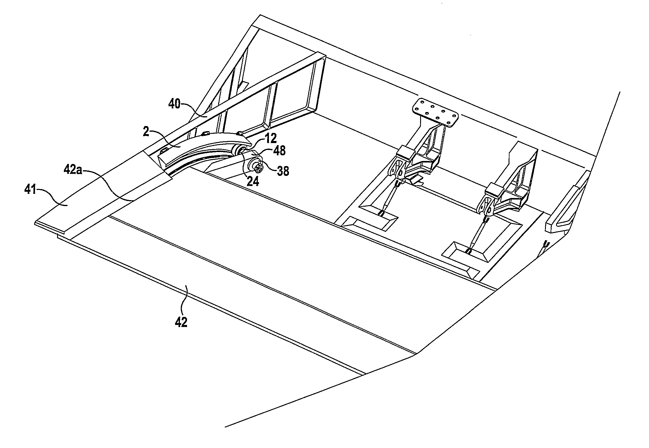
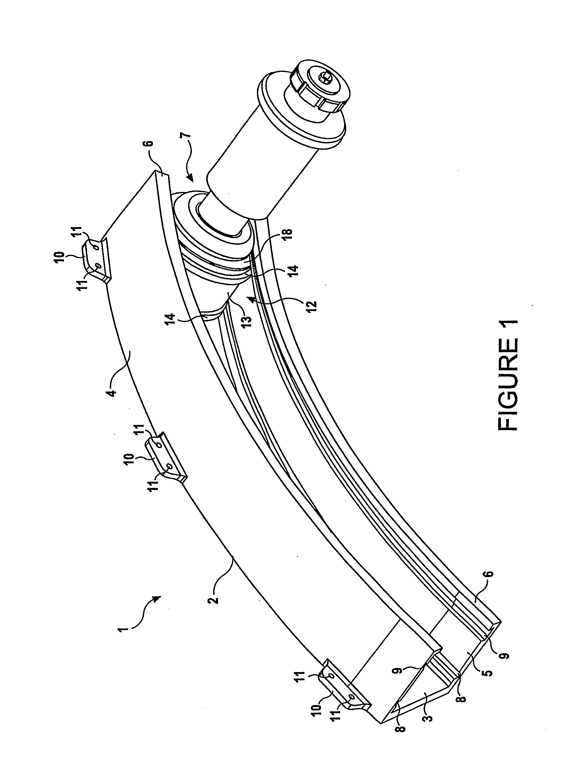
[0049]Referring now to the drawings, there is shown in FIG. 1 a perspective view of a support assembly 1 for guiding the end of a flap 42 (see FIG. 9) on an aircraft wing 41 during deployment of the flap 42. The support assembly 1 comprises an arcuately shaped guide track 2 which is open at both ends and has a generally “C”-shaped cross-sectional profile defined by a rear wall 3 and two curved side walls 4,5 that are parallel to each other and extend forwardly of the rear wall 3. The front edge of each side wall 4,5 terminates in a lip 6 that extends inwardly towards the opposite side wall 4,5. A series of flanges 10 upstand from the rear edge of the upper side wall 4 to enable the guide track 2 to be immovably attached to either the false work rib or internal wing structure 40 (see FIG. 9) of an aircraft wing 41 or, to the flap or an extension of the flap using, for example, bolts (not shown) passed through holes 11 in each flange 10.

[0050]A pair of spaced parallel grooves 8, 9 are...


PUM


Abstract

A support assembly (1) for guiding a flap (42) on an aircraft wing (41) during deployment of the flap is disclosed. The assembly comprises a guide track (2) defining a two-dimensional path, a cylindrical bearing follower (12) having a longitudinal axis constrained so as to follow said path during flap deployment, a shaft (23) extending from the bearing follower and, a spherical bearing coupling an end of the shaft to the bearing follower such that the bearing follower is rotatable relative to the shaft about the longitudinal axis of the bearing follower as it travels along the track. The spherical bearing also enabling rotation of the shaft about its longitudinal axis relative to the bearing follower and rotation of the shaft about a centre point of the spherical bearing such that the flap is fret to move in multiple directions.

Description

FIELD OF THE INVENTION [0001]The present invention relates to a support assembly for guiding a flap on the wing of aircraft during deployment of the flap from the wing. The assembly includes a bearing which is capable of guiding and supporting the flap throughout a wide range of movement.BACKGROUND [0002]A flap on an aircraft is attached to the wing at each end of the flap. A flap end support must allow for multiple degrees of freedom of movement of the flap whilst supporting the flap throughout that movement. The primary direction of movement of a flap during deployment and stowage may require it to follow an arcuate path. However, in addition to its primary direction of movement, secondary movements in other directions may also occur due to, for example, misalignments caused by wing bending which can induce axial changes in the length of the wing assembly, all of which must be accommodated for in the flap support.[0003]In larger aircraft, the flaps may be required to follow a more...

Claims


Application Information

Patent Timeline
Patent Type & Authority Applications(United States)
IPC IPC(8): B64C9/02
CPCY02T50/44B64C9/16F16C13/006F16C19/18F16C23/086Y02T50/40
Inventor PARKER, SIMON
Owner AIRBUS OPERATIONS LTD
Why Eureka
Try Eureka