Plasma Display Panel Characterized by High Efficiency

a technology of display panel and phosphor layer, which is applied in the direction of gas-filled discharge tubes, discharge tubes/lamp details, incadescent body mounting/support, etc., can solve the problems of low visible light extraction efficiency, failure to effectively excite the phosphor layer, and insufficient thickness of the phosphor layer, etc., to achieve high efficiency, low power, and high luminous brightness

Inactive Publication Date: 2011-03-03
SAMSUNG SDI CO LTD
View PDF16 Cites 0 Cited by
  • Summary
  • Abstract
  • Description
  • Claims
  • Application Information

AI Technical Summary

Benefits of technology

[0008]One or more embodiments of the present invention include a highly efficient plasma display panel (PDP) which can be driven with low power and obtain high luminous brightness.

Problems solved by technology

Because flowable phosphor paste sags and flows down from the side surfaces of the barrier walls, the phosphor layer is not formed with a sufficiently large and uniform thickness.
Consequently, visible light extraction efficiency is low.
Furthermore, since bottom surfaces of the discharge cells on which the phosphor material is concentrated are relatively far from the front substrate where the discharge electrodes are arranged, a sufficient amount of UV light does not reach the phosphor layer and thus fails to effectively excite the phosphor layer.
Since an address discharge occurs along a long discharge path corresponding to the height of a discharge cell, a high address driving voltage is required, and a sufficient voltage margin is not obtained.

Method used


Image

  • Plasma Display Panel Characterized by High Efficiency
  • Plasma Display Panel Characterized by High Efficiency
  • Plasma Display Panel Characterized by High Efficiency

Examples


Embodiment Construction

[0024]Reference will now be made in detail to embodiments, examples of which are illustrated in the accompanying drawings, wherein like reference numerals refer to like elements throughout.

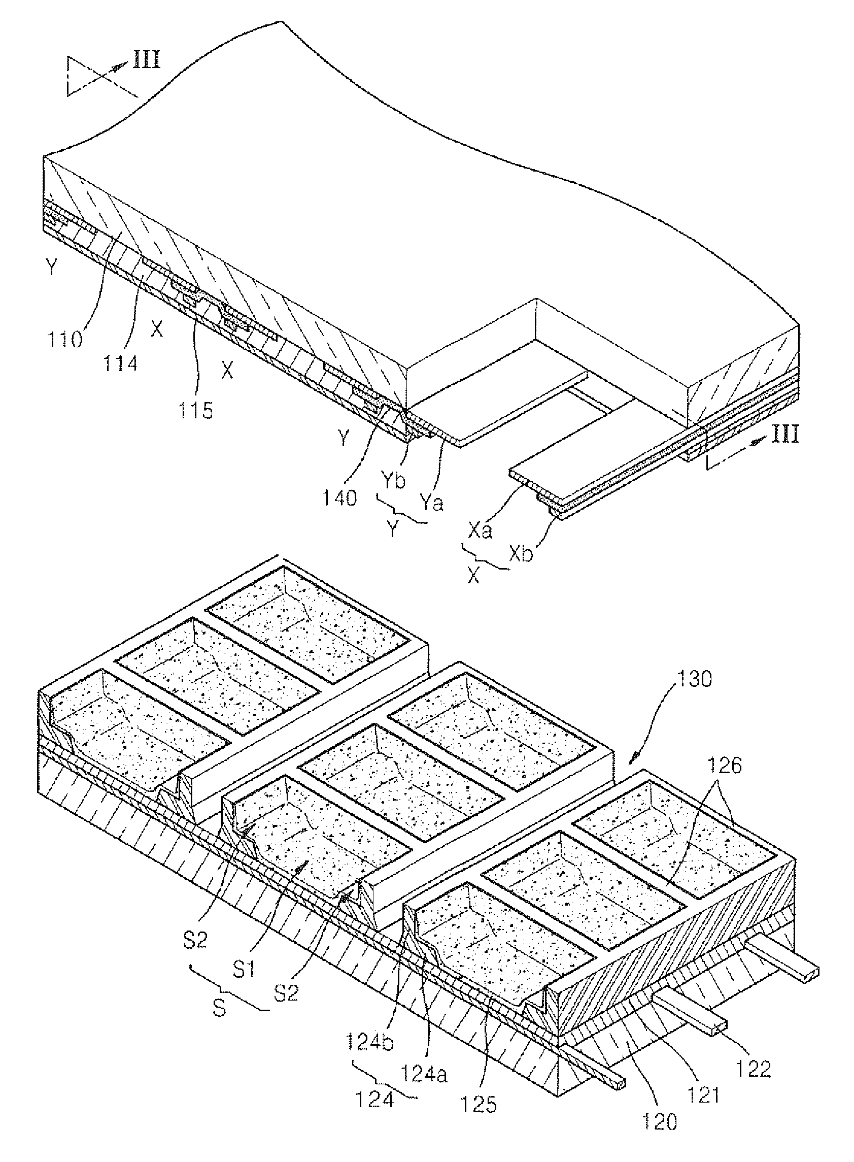
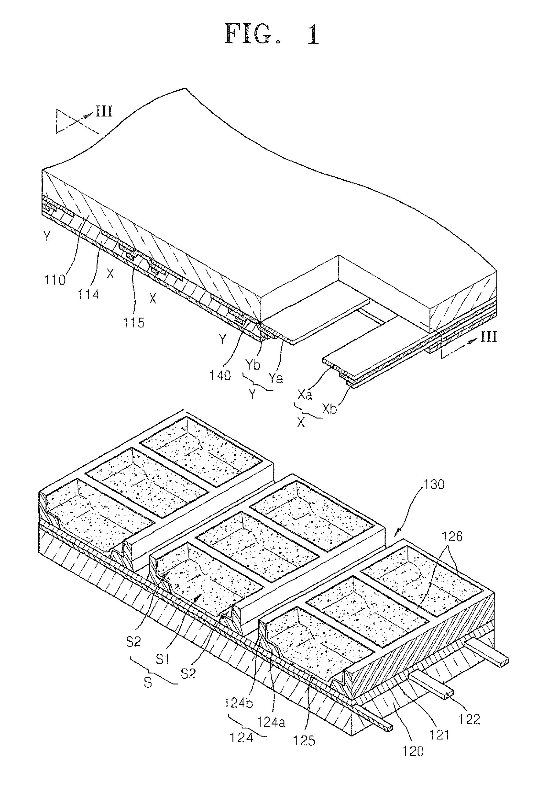
[0025]FIG. 1 is an exploded perspective view of a plasma display panel (PDP) according to an embodiment of the present invention.

[0026]Referring to FIG. 1, the PDP includes a front substrate 110 and a rear substrate 120 which face each other with an interval there between, and barrier walls (including horizontal barrier walls 124 and vertical barrier walls 126) which define a plurality of unit cells S. For example, the barrier walls include the horizontal barrier walls 124 extending in one direction and the vertical barrier walls 126 extending so as to cross the extending direction of the horizontal barrier walls 124, and thus define unit cells S which are quasi-rectangular.

[0027]For example, each unit cell S denotes a minimal light-emitting unit which includes a discharge electrode pair (X,Y) for...


PUM


Abstract

A plasma display panel (PDP) comprises: a front substrate and a rear substrate which face each other; and a barrier wall which is interposed between the front substrate and the rear substrate, which includes base portions arranged on either side of a main discharge space, and protruding portions protruding on the base portions, respectively, and which defines stepped spaces on either side of the main discharge space. The stepped spaces are formed according to stepped surfaces formed by the base portions and the protruding portions. The PDP further comprises a pair of a scan electrode and a sustain electrode which generate a mutual discharge through the main discharge space. A channel space is defined by outer walls of the protruding portions on either side of the main discharge space, and an external light absorbing layer covers the channel space.

Description

CLAIM OF PRIORITY[0001]This application makes reference to, incorporates the same herein, and claims all benefits accruing under 35 U.S.C. §119 from an application earlier filed in the Korean Intellectual Property Office on Aug. 28, 2009 and there duly assigned Serial No. 10-2009-0080697.BACKGROUND OF THE INVENTION[0002]1. Field of the Invention[0003]The present invention relates to a plasma display panel (PDP) and, more particularly to a highly efficient PDP which can be driven with low power and obtain high luminous brightness.[0004]2. Description of the Related Art[0005]Plasma display panels (PDPs) are a type of flat display devices that form images by using visible light produced from a phosphor material excited with ultraviolet (UV) rays generated by a plasma discharge.[0006]In the PDPs, a front substrate having discharge electrodes arranged thereon and a rear substrate having address electrodes arranged thereon are attached to each other so as to face each other by interposing...

Claims


Application Information

Patent Timeline
Patent Type & Authority Applications(United States)
IPC IPC(8): H01J17/49
CPCH01J11/12H01J11/36H01J2211/444H01J2211/363H01J11/44H01J11/34
Inventor HWANG, EUI-JEONGPARK, HYOUNG-BINJEON, SANG-HOSON, SEUNG-HYUNKIM, HYUN-CHULKIM, HYEON-SEOKYUN, BOK-CHUNJEONG, SIL-KEUNKIM, JUNG-MINCHOI, SUNG-HYUNAHN, SANG-HYUCKCHO, SUNG-HEEKIM, GI-YOUNGKIM, MYOUNG-SUPLEE, HYE-JUNG
Owner SAMSUNG SDI CO LTD
Why Eureka
Try Eureka