
Vehicle head light device

a head light and vehicle technology, applied in the direction of fixed installation, lighting and heating equipment, lighting support devices, etc., can solve the problems of greatly increasing and the manufacturing fee or cost of the vehicle head light device will be greatly increased, so as to achieve suitably reduced manufacturing and assembly costs, and easy and fast manufacturing and assembly

Inactive Publication Date: 2011-03-03
SHIH JEN SHIEH
View PDF12 Cites 20 Cited by
  • Summary
  • Abstract
  • Description
  • Claims
  • Application Information

AI Technical Summary

Benefits of technology

"The present invention provides a vehicle head light device with a simplified structure that allows for easy and quick manufacturing and assembly, and reduces manufacturing costs. The device includes an outer housing with a chamber, an inner housing with an upper and lower casing, and a hood. The inner housing also has a passage for air circulation. The device also includes circuit boards with light members directed toward the reflective members of the upper and lower casings for generating lights. The hood has an opening for air to flow through. The device also includes heat dissipating devices for positioning the circuit boards, and a frame for securing the hood and inner housing to the outer housing. The technical effects of the invention are simplified manufacturing and assembly, reduced manufacturing costs, and improved heat dissipation."

Problems solved by technology

However, the typical vehicle head lights comprise a complicated structure that may not be easily and quickly manufactured and assembled and the manufacturing fee or cost of the vehicle head light device will be greatly increased.
However, the typical vehicle headlamp also comprises a complicated structure that requires an actuator for moving the movable shade around a rotary axis and that also may not be easily and quickly manufactured and assembled and that the manufacturing fee or cost of the vehicle head lamp device will be greatly increased.

Method used


Image

  • Vehicle head light device
  • Vehicle head light device
  • Vehicle head light device

Examples


Embodiment Construction

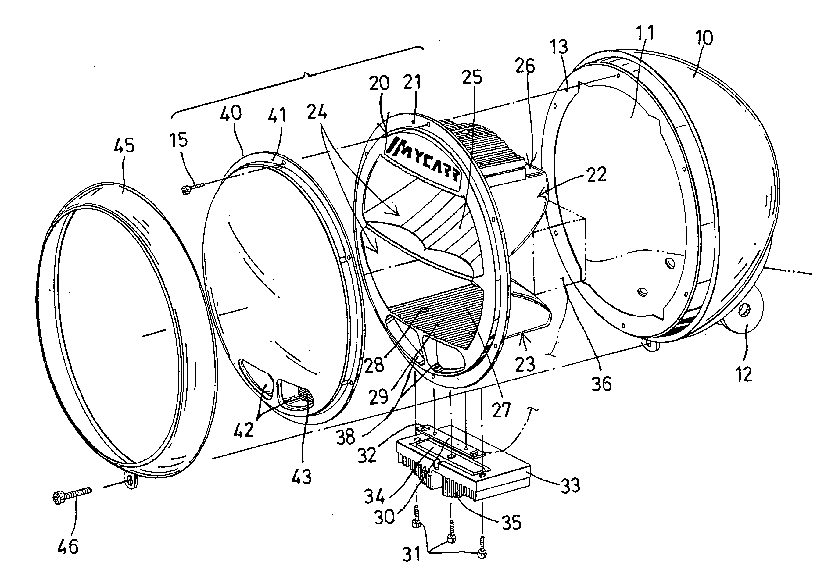
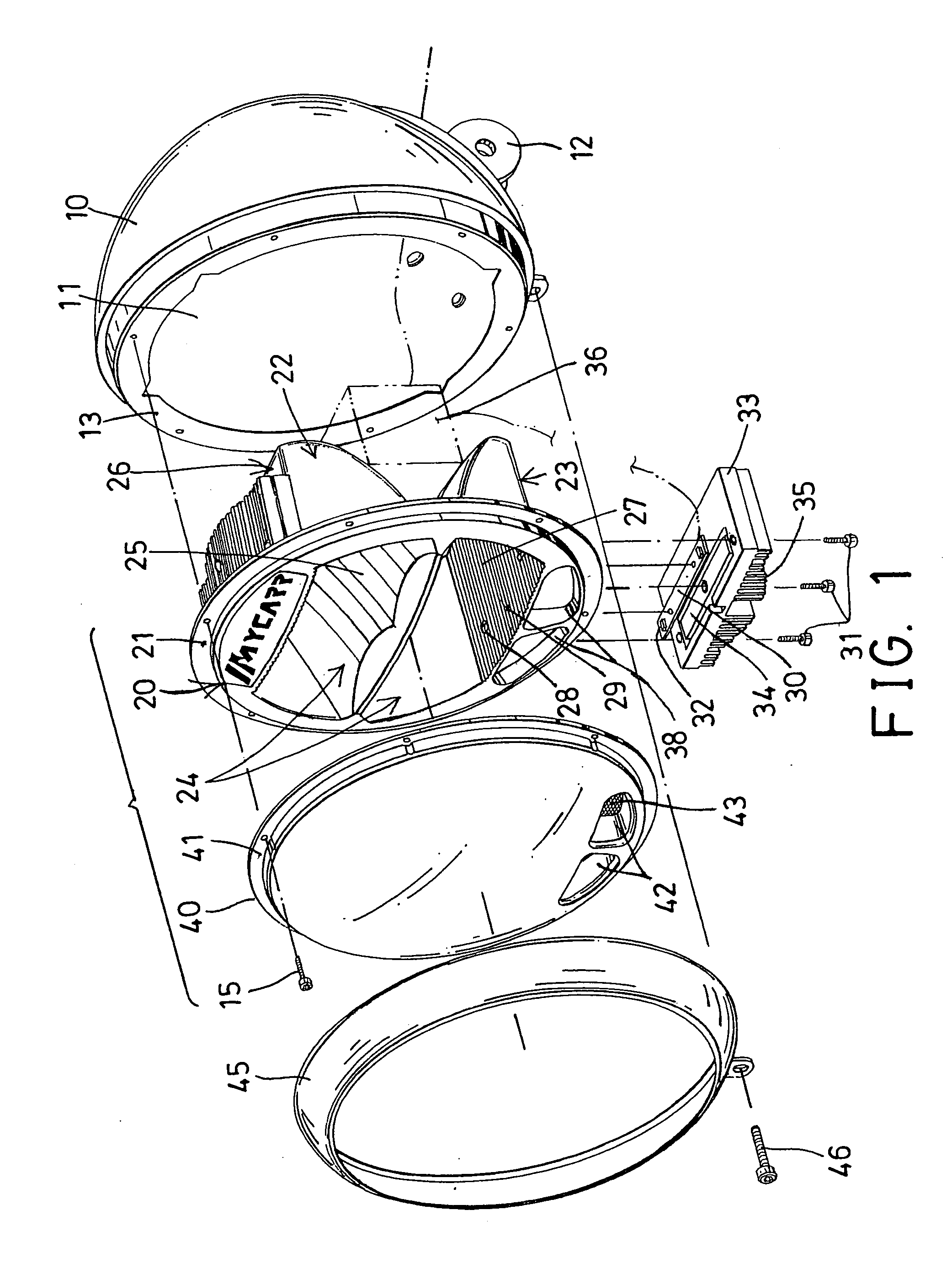
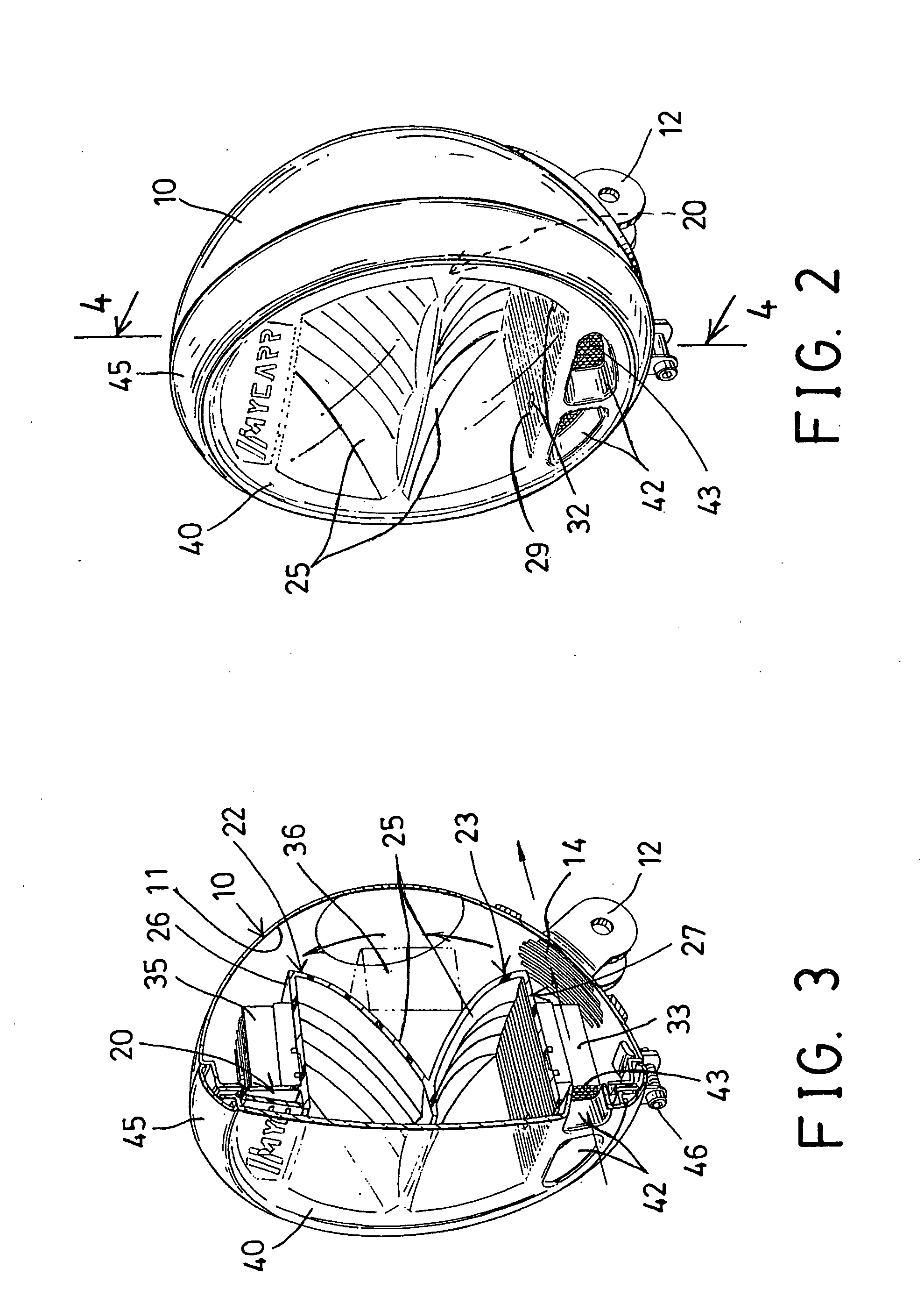
[0026]Referring to the drawings, and initially to FIGS. 1-4, a vehicle head light device in accordance with the present invention comprises an outer housing 10 including a dome-shape having a chamber 11 formed therein, and including one or more ears 12 extended outwardly therefrom for attaching or mounting or securing to the front portion of a vehicle, for example, and including an outer peripheral flange 13 formed or provided in the front portion of the outer housing 10 and extended radially and inwardly into the chamber 11 thereof, and including a number of air perforations 14 formed therein, such as formed in the rear and / or lower portion of the outer housing 10, best shown in FIGS. 3-5, for allowing the air to flow into or out of the outer housing 10.

[0027]An inner housing 20 is disposed in the chamber 11 of the outer housing 10 and / or attached to the front portion of the outer housing 10, and includes an outer peripheral flange 21 formed or provided in the front portion of the ...


PUM


Abstract

A vehicle head light device includes an inner housing attached to front of an outer housing and having an upper casing and a lower casing located within the outer housing, and the casings each include a reflective member, two circuit boards are attached to the casings and each include one or more light members directed toward the reflective members for generating lights toward the reflective members which reflect the lights to form a high beam and a low beam respectively, a control device is disposed in the outer housing and electrically coupled to the circuit boards for controlling the light member to generate the lights toward the reflective members of the casings respectively.

Description

BACKGROUND OF THE INVENTION[0001]1. Field of the Invention[0002]The present invention relates to a vehicle head light device, and more particularly to a vehicle head light device including a simplified structure for allowing the vehicle head light device to be easily and quickly manufactured and assembled and for allowing the manufacturing fee or cost of the vehicle head light device to be suitably reduced.[0003]2. Description of the Prior Art[0004]Typical vehicle head light devices comprise a central light bulb disposed in a light housing, and one or more reflective or refracting members for reflecting the light.[0005]For example, U.S. Pat. No. 6,650,058 to Wang discloses one of the typical vehicle head lights comprising an inner housing and an outer housing, a light passage channel formed and located between the inner and the outer housings, a central light bulb disposed in the inner housing, and two auxiliary light bulbs disposed in the outer housing, and a complicated electrical...

Claims


Application Information

Patent Timeline
Patent Type & Authority Applications(United States)
IPC IPC(8): B60Q1/00F21V15/01
CPCF21S48/1159B60Q1/0041F21S41/663F21S45/49F21S41/148F21S45/48F21S41/19
Inventor SHIH, JEN SHIEH
Owner SHIH JEN SHIEH
Learn More