Solar Cell Defect Passivation Method

a solar cell and defect technology, applied in the field of solar cell defect passivation, can solve the problems of less improvement of crystalline silicon solar cell and a-si solar cell with single junction due to process stress, and may be found in the final product manufacturing, basic electric elements, climate sustainability, etc., to achieve the effect of improving photovoltaic conversion efficiency

Active Publication Date: 2011-03-03
INST NUCLEAR ENERGY RES ROCAEC
View PDF1 Cites 16 Cited by
  • Summary
  • Abstract
  • Description
  • Claims
  • Application Information

AI Technical Summary

Benefits of technology

The technical effect of this patent is that it describes how treating solar cells with hydrogen can improve their ability to convert light into electricity. This helps increase the amount of sunlight that these cells are able to capture and use in generating energy.

Problems solved by technology

The technical problem addressed in this patent text is the improvement of photovoltaic conversion efficiency in solar cells, particularly in crystalline silicon and a-Si solar cells, by addressing defects in the solar cell that can occur after fabrication. The text discusses various techniques and facilities for fabricating solar cells, as well as the limitations of current methods for passivating defects, such as hydrogen plasma ion implantation. The text also highlights the challenges in improving the efficiency of multi-junction solar cells due to increased interface and crystalline defects. The text concludes by stating that current methods for improving photovoltaic conversion efficiency in solar cells are not fully effective and require further improvement.

Method used


Image

  • Solar Cell Defect Passivation Method
  • Solar Cell Defect Passivation Method
  • Solar Cell Defect Passivation Method

Examples


Embodiment Construction

[0022]The following descriptions of the preferred embodiments are provided to understand the features and the structures of the present disclosure.

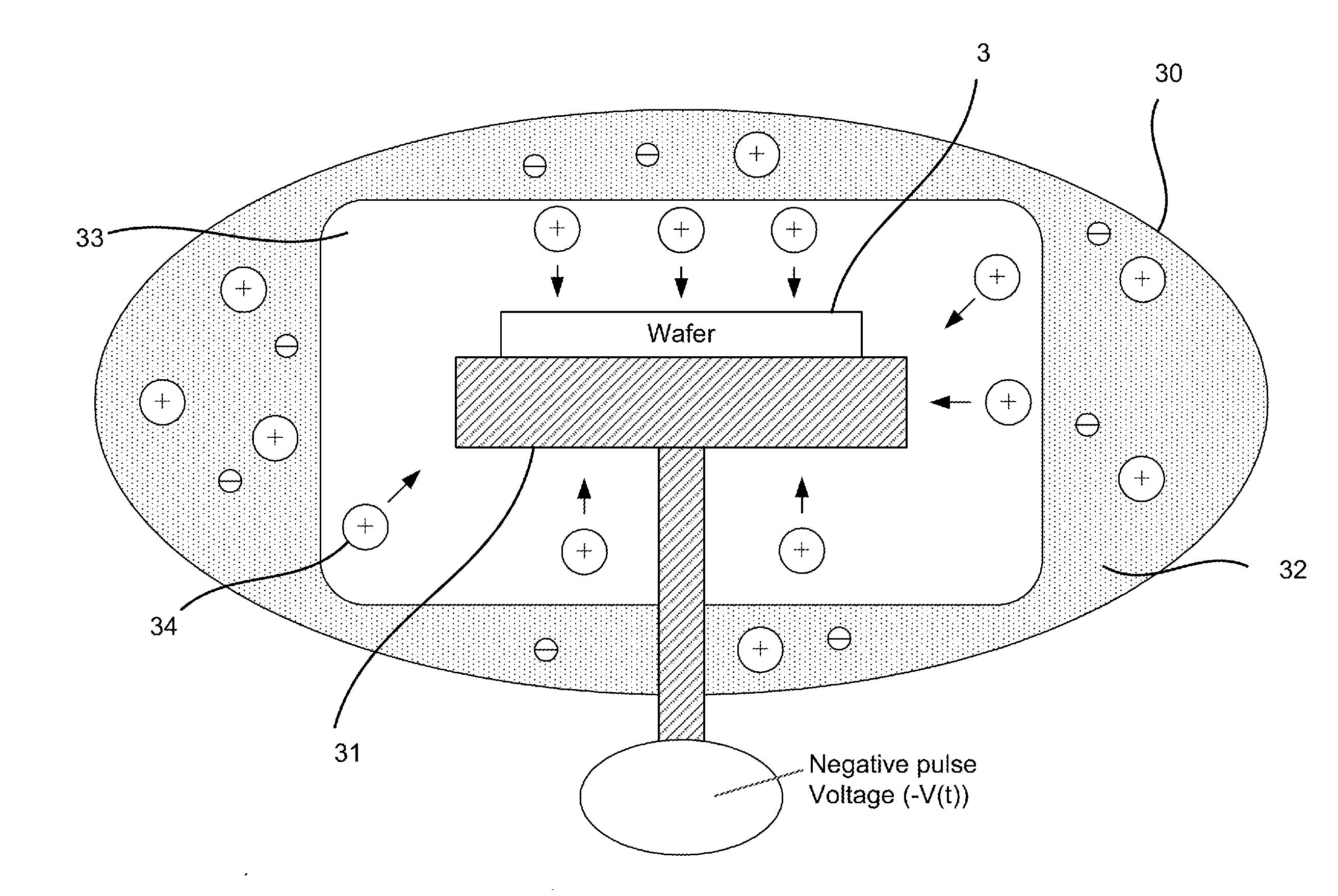
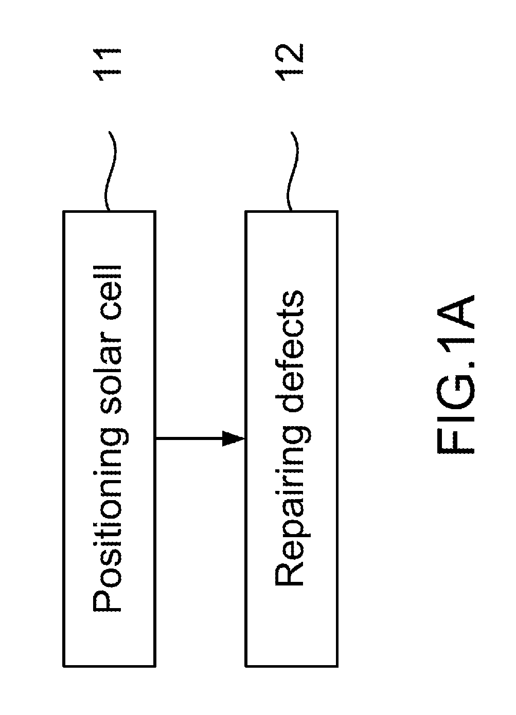
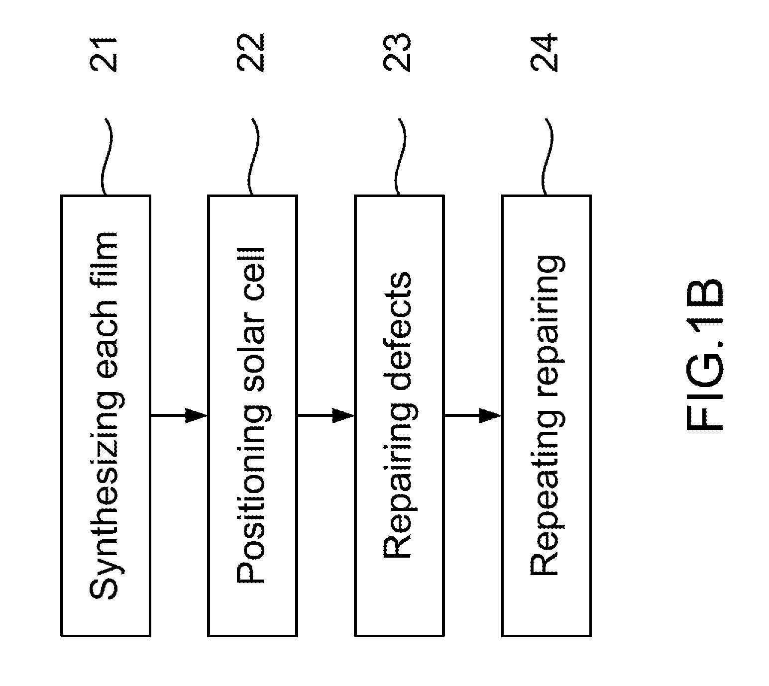
[0023]Please refer to FIG. 1A and FIG. 1B, which are flow views showing a first preferred embodiment and a second preferred embodiment according to the present disclosure. As shown in the figures, the present disclosure is a solar cell defect passivation method, where plasma immersion ion implantation (PIII) is used to repair defects of a solar optoelectronic device. In a first preferred embodiment, a passivation process for repairing defects of a wafer solar cell through ion implantation comprises the following steps:

[0024](a1) Positioning solar cell 11: A solar optoelectronic device is put into a PIII device, where the solar optoelectronic device is a wafer solar cell made of crystalline silicon or polycrystalline silicon.

[0025](b1) Repairing defects 12: A plasma of an ion is selected to three-dimensionally repair defects of the solar o...


PUM


Abstract

The present disclosure passivates solar cell defects. Plasma immersion ion implantation (PIII) is used to repair the defects during or after making the solar cell. Hydrogen ion is implanted into absorption layer with different sums of energy to fill gaps of defects or surface recombination centers. Thus, solar cell defects are diminished and carriers are transferred with improved photovoltaic conversion efficiency.

Description


Claims


Application Information

Patent Timeline
Owner INST NUCLEAR ENERGY RES ROCAEC
Why Eureka
Try Eureka